Close
0%
0%

ItsyBitsy Tomato Timer

This is my second PCB. It will function primarily like a Pomodoro timer.

Similar projects worth following
This is going to be a Pomodoro timer (25 minute productivity hack). Each LED will represent 5 minutes. When I set the timer, they'll all be lit, and one will go dark every 5 minutes.

I really like the Pomodoro Technique, and I currently use a Circuit Playground Express that's programmed to function as one. I think this will operate basically the same way.


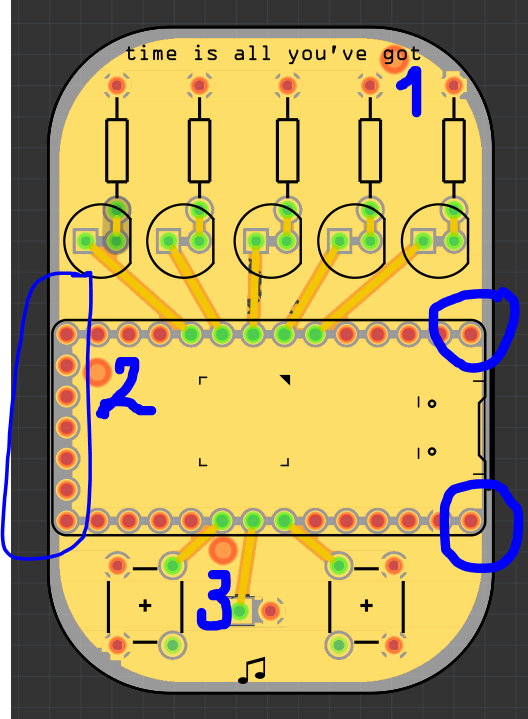
Each LED represents 5 minutes. One button will add time in 10 minute increments, and the other in 5 minute increments, because sometimes I like to do cherry tomatoes and grape tomatoes instead of full 25-minute beefsteaks.

Starting the timer on the Circuit Playground works like this: I press both buttons and then release one. This starts the countdown, and the LEDs go dark one by one every 5 minutes. At the end of the time, a short victory song plays. I imagine this one will start the timer the same way.

Games!

Okay so I have one game idea, and it's basically LED whack-a-mole. At the beginning of the game, the game chooses one LED as the target and blinks it to let you know which one. Then it goes back and forth quickly lighting the LEDs one by one, and the object is to press the button when the target LED is lit.

x-zip-compressed - 163.90 kB - 12/26/2019 at 03:01

Download

  • 1 × ItsyBitsy M0
  • 5 × red LEDs
  • 5 × resistors
  • 2 × momentary buttons
  • 1 × piezo buzzer

  • This is what victory looks like!

    kristina panos01/23/2020 at 02:28 1 comment

    This is what happens when the time is up. Victory song pending.

  • Lessons Learned: Ground Planes Edition

    kristina panos01/06/2020 at 03:08 0 comments

    This is my second PCB ever, so I'm still constantly learning things. Here's something I didn't realize until the boards showed up and didn't have continuity -- I had multiple, unconnected ground planes because my board was designed to be barely wider than the ItsyBitsy. I now realize that all I had to do was count the red copper fill connector thingies that I've numbered below. 

    If the board were 1/8" or so wider, this wouldn't have been a problem at all. So, now I have a wire on the back connecting the top and bottom ground planes. There are actually three ground planes total, with the third being underneath the IB. I don't need that one, so it's not getting a wire.

  • Drop everything and solder

    kristina panos01/05/2020 at 03:50 0 comments

    Boards came this afternoon, so I've got this up and running now:

  • ItsyBitsyTomato-v1 sent to fab

    kristina panos12/27/2019 at 14:23 0 comments

    OSHPark emails are my new favorite emails! Boards are expected back from fab on January 2nd. I think I have all the parts . . .

View all 4 project logs

Enjoy this project?

Share

Discussions

phillicom wrote 12/24/2019 at 22:39 point

Hi Kristina,

There appears to be a track between both pins of the piezo.  Perhaps this will short the piezo and give the software a reason for adding both pins to the ground plane.  If the piezo pins need to be connected, you might like to try using copper fill instead of ground fill.

  Are you sure? yes | no

kristina panos wrote 12/24/2019 at 23:56 point

D'oh! That was it! I don't know where that wire came from, but removing it solved the problem. Thank you!! I'm putting up a new picture. 

  Are you sure? yes | no

phillicom wrote 12/25/2019 at 22:22 point

Happy to help. It is very easy to add a track in Fritzing and, while this feature makes Fritzing easier to use, it can sometimes bite if the user is in a hurry. I'm a regular with the undo create track button.

  Are you sure? yes | no

Simon Merrett wrote 12/24/2019 at 22:37 point

Hi @kristina panos are you using fritzing? I'm afraid I don't know fritzing for pcb layout but I have an idea that may help. As you have plenty of gpios free, could you make the ground pin for the piezo connect with a gpio that you then set as output low, rather than connecting it to the schematic ground signal? So both piezo pins not connected to ground and each one connects to one separate gpio. Might avoid the anomaly you're experiencing by trying to connect with a ground plane. In this case, you only need one of your gpios to remain isolated, so even if one erroneously connects to the ground plane, that then becomes your ground. If both pins then become isolated from the ground plane, you can make one a ground in software or drive it push-pull for extra volume. 

  Are you sure? yes | no

kristina panos wrote 12/25/2019 at 00:29 point

Hi @Simon Merrett yes I am. That is an interesting idea. Thank you for your comment! However the problem is now solved -- it was as simple as a misplaced wire between the piezo pins. I could swear I deleted and re-added the piezo at one point, so I really don't know where it came from.

KiCad here I come, I guess!

  Are you sure? yes | no

Simon Merrett wrote 12/25/2019 at 08:41 point

Glad you solved it @kristina panos . Good to hear you're keen to try kicad. The kicad forums are a helpful resource if you hit any issues. 

  Are you sure? yes | no

Similar Projects

Does this project spark your interest?

Become a member to follow this project and never miss any updates