UTSOURCE
Transmitter Connections :
The operation voltage of RF transmitter is : (3.3v - 5 v)
PINOUT OF HT12E (ENCODER)-
Pin 1-8: Assignment of receiver direction, it mean it can changing of addresses for communication individually if is needed
9. VSS connected to GND
10-13. AD in this pins is for to transmitting data of 3 bits (in our case to the receptor)
14. Transmission enable, it can be done connecting this pin to GND
15-16. In this ports it have to put a "oscillation resistor" very very important use the value of 1 M ohm
17. This pin have to be connected to Data pin of our 433 MHz RF transmitter.
18. This pin goes connected to VCC or our positive terminal of our power supply or battery
Receiver Connections :
PINOUT OF HT12D (DECODER)-
1-8. Connected to gnd for enable communication with the HT12E
9. VSS this pin goes to GND.
10-13. "AD" the IC use this pins for the output data that is sent with the transmitter, in our case led for indicating receiving info and direct output for to connect a relay or anything you want.
14. "DIN" this pin goes connected to DATA of our 433 MHz RF receiver.
15-16. In this ports goes connected a resistor with a value of 68 k ohms or very very close value like 70 k or 60 k (IMPORTANT: Don't change the value of this resistor if you make that your circuit it doesn't work).
17. No connection.
18. this pin goes to VCC or the positive of our power source.
Range :
The RF transmitter with and a good antenna can sent data up to 500 ft (outdoor and no osbtacles)
The operation voltage of RF transmitter is : (3.3v - 5 v)
The operation voltage of RF receiver is: (5v - 9v).
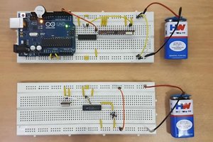
After connecting everything as mentioned above and shown in schematics/images attached then connect the power and after that if you change the state of Switches at transmitter so the LEDs corresponding to those switches on Receiver will turn ON as shown in images.
 icstation