 Ken Yap
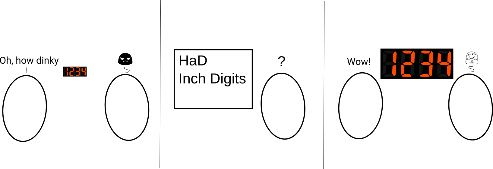
I decided to find out how large a 4-digit LED display I could fit into a budget 100x100 mm PCB, and how much it would cost, so that I can make future projects with large digits.
LED displays, with or without driver chips onboard, are cheap these days. But the usual offerings are in small sizes, e.g. 0.36 in, 0.56 in. Even back in the days of abysmal LED efficiency, I had 20 mm tall digits. You can of course buy large digits. They are more likely to be single digit displays as the size increases. Perhaps the yield goes down when combining digits. But using multiple packages in multiplexing is not a problem if you have a PCB to take care of wiring all the segments together.
Goals
- Pack the largest 4 digits possible on a 100x100 mm board
- Incorporate a driver on board to simplify interfacing
- Learn to solder SMT parts
- Learn to use FreeCAD and KicadStepUpMod to generate a step model (added goal)
- Learn to use Inkscape to draw cartoons (added goal)
The quest
It was about the time that I was checking out LCSC. To make the shipping an acceptable fraction of the total cost I had to make a large order.
The ARKLED SM411006N/15 1 in red display is cheap at $0.25 (all prices in USD). I ordered 40 to make 10 boards.
The TM1637 driver chip is only $0.15. It comes in a SOP20 package that will give me practice with soldering SMT. I ordered a dozen so that I can put a couple on breakout boards for breadboarding, and use the rest for production.
The circuit design
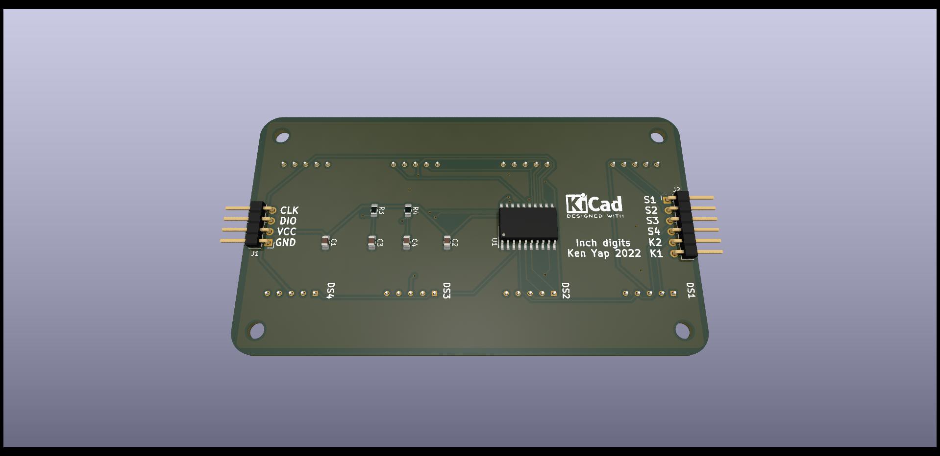
The design is straight out of the TM1637 datasheet. I aimed for compatibility with the existing 0.36 in TM1637 display boards you can buy for about $1 from China, down to the 4 pin header so that it can be an electrical replacement for those.
After I received the displays I tested them and found that the forward voltage is about 3.6 V, which indicates that each segment has 2 diodes in series, except for the decimal point. This was a worry as I wondered if there was enough margin from a 5 V supply for the chip to drive the displays. Another strange thing about the circuit was the absence of current limiting resistors. I think there is a constant current circuit on chip that also takes care of the variation in LED voltage. They don't tell you some things in Chinese datasheets. The chip supports software brightness control. At maximum brightness it was acceptable, although not as bright as I had hoped. It's hard to beat a high-intensity LED display, plasma, or nixies for brightness.
The TM1637 also handles up to 16 switches, which are omitted in cheap display boards. Since I had a lot of board space available I designed in 8 switches. The positions don't have to be populated if the application doesn't need switches.
One drawback of this design is that there is no colon display for clocks. You could use a decimal point, and blink that too. In my preferred 24 hour clock, the colon is redundant, unless you need to distinguish between HH:MM and MM.SS.
You'll also notice that the displays jut outside the bounds of the PCB. This is no concern if the display is behind a panel. The pins are well within the PCB.
I tested the circuit on a breadboard using a familiar TM1637 sketch for Arduino that implements a 4 digit counter. I didn't actually wire up 4 displays, but rather used a jumper lead to select which digit to display. The units digit was a blur, the hundreds fast enough to see the increment, and the thousands slow enough to take a photo.
PCB fabrication
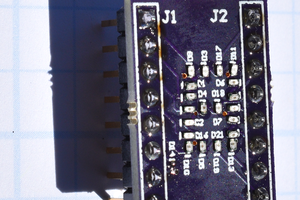
I sent the Gerber files to PCBWay who I have used in the past. There was a Nov-Dec offer so I just managed to finish verifying the circuit design before the new year. The PCB I had designed well ahead of time. The boards came back in about 2 weeks. The board is the first one I've made using SMT. For the breadboard I was able to solder a TM1637 on a breakout board with a little practice, but as I had not planned ahead to get tweezers for the 4 SMT passives, have to delay assembly.
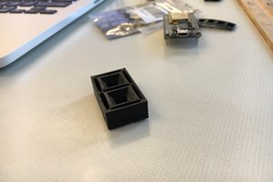
3D model
LCSC has links to download...
Read more »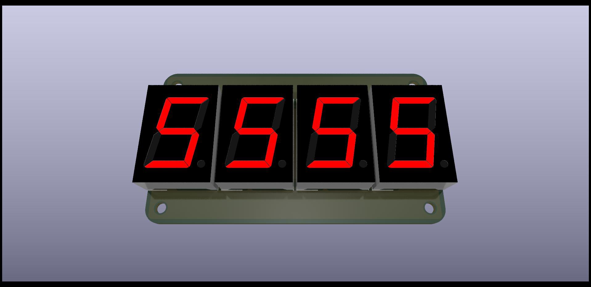
 Bharbour
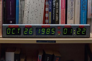
 Stephen Holdaway
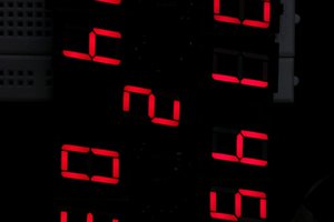
 Maksim Surguy