Pros of my project?
- very affordable, cheap electronics and other parts;
- opensource web server for easy management;
- accurate time from ntp server;
- it is possible to have multiple languages;
- minute by minute time indication (not by 5 minutes like standard word clocks), dynamic time display and amazing flexibility for future ideas...
I.The Enclosure
Wooden photo frame
 |  |
You can make your own frame, there are a dozen of articles about this, everywhere on the net. But a simpler solution would be finding a framing company where you can order a personalized frame with your required dimensions and you can choose from many frame types. This is exactly what I did. I ordered my frames with a specific dimension: the framed photo, in my case object (display) is 80x80mm. I also asked for an accurate dimension, I didn't want the frame to be too big for the 3D printed plastic grid.
Plexiglass support

The plexiglass support can be also be made DIY but for an amateur it is not very easy to cut and blend plexiglass. So I ordered several supports from an advertising company that makes all kinds of plexiglass objects. The dimensions I used are: width - 120mm, first part length - 180mm, second part length - 50mm, 15° bending angle.
Display plexiglass sheet

The 3mm grey smoked plexiglass sheet can be cut from a bigger sheet, obtaining the required 80x80mm dimension.
Plastic grid

The STL file for 3D printing can be downloaded from Tinkercad
Display Printed Paper Sheet

The SVG file for the Printed Paper Sheet is attached, and it can be edited with Inkscape. You can make your own display layout based on this SVG file, I used Word Search Construction Kitsoftware to generate a words layout for the time display. You can print the file repeatedly on the same sheet of paper to achieve a good, opaque, black background. I got very good results with a cheap inkjet printer and standard white copier paper. I cut off the layout with a pair of scissors.
Plastic box for electronics

The files that you can 3d print are also on Tinkercad. I used some already purchased jewelry boxes, I only designed a new box base because the boxes were too tall. The files on Tinkercad are based on this type of boxes.
II.The Electronics
ESP-01 board

Cheap and versatile microcontroller module with WiFi capability, if you don't know about it there are many howto's on the net. (For example you can read this good instructable by TonesB ESP8266 WiFi Module for Dummies)
3.3v stabilizer module

The ESP-01 requires to be powered with 3.3v, I used here a 4pin module.
Led Matrix 64led RGB Matrix with WS8212 IC

You can read more in Getting Started With NeoPixel / WS2812 RGB LED by Open Green Energy.
3 Pin Header and connector

I used this connector because it permits easy assembly-disassembly of the enclosure.
DC connector and DC power supply
 |  |
The power supply is 5v and 1.5A maximum, it is rather enough because not all leds are lightened up at full brightness and full white. Also I opted for a separate DC connector because it is simple to replace a defective power supply
Schematics - Very simple, made with Fritzing, see the image bellow.

III.Programming the ESP-01 Board
My way for flashing the ESP-01 is using an adapter with a PL2303 chip (USB to Serial converter). Also to make the programming easier, I used a breadboard adapter like this and I connected it to the USB to Serial converter. You can see in the images the wiring between these two modules: 3.3v-RED, Ground-BLACK, RX from the converter to TX on adapter-PURPLE, TX from the converter to RX on adapter-GREY. On the adapter I soldered a switch (PROG) between GPIO0 and GND pins and a switch (RESET) between RST and GND pins.

 |  |
IV.Configuring and Using the Clock
After correctly flashing the ESP-01 module, start the clock. On the display you will see an animation like bellow.
You will find a new WiFi Access...
Read more »


 clewsy
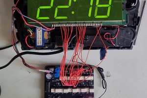
 zst123
 Thomas Flayols
 Roni Bandini
The 8x8 RGB LED Matrix Desktop Word Clock is a unique time-telling device that utilizes an array of LEDs to display the current time using words instead of traditional numbers. Each LED corresponds to a specific time unit (hours and minutes), lighting up to form words that indicate the time in a readable format. This innovative clock offers a stylish and modern way of visualizing the time, making it both functional and aesthetically pleasing as a desktop or wall-mounted clock. An example of a useful tool that could complement this clock is an online contador de palabras online, which assists in various writing tasks by accurately tallying the number of words in a given text, ensuring precision and adherence to specific word count requirements for content creation or editing purposes.