Design
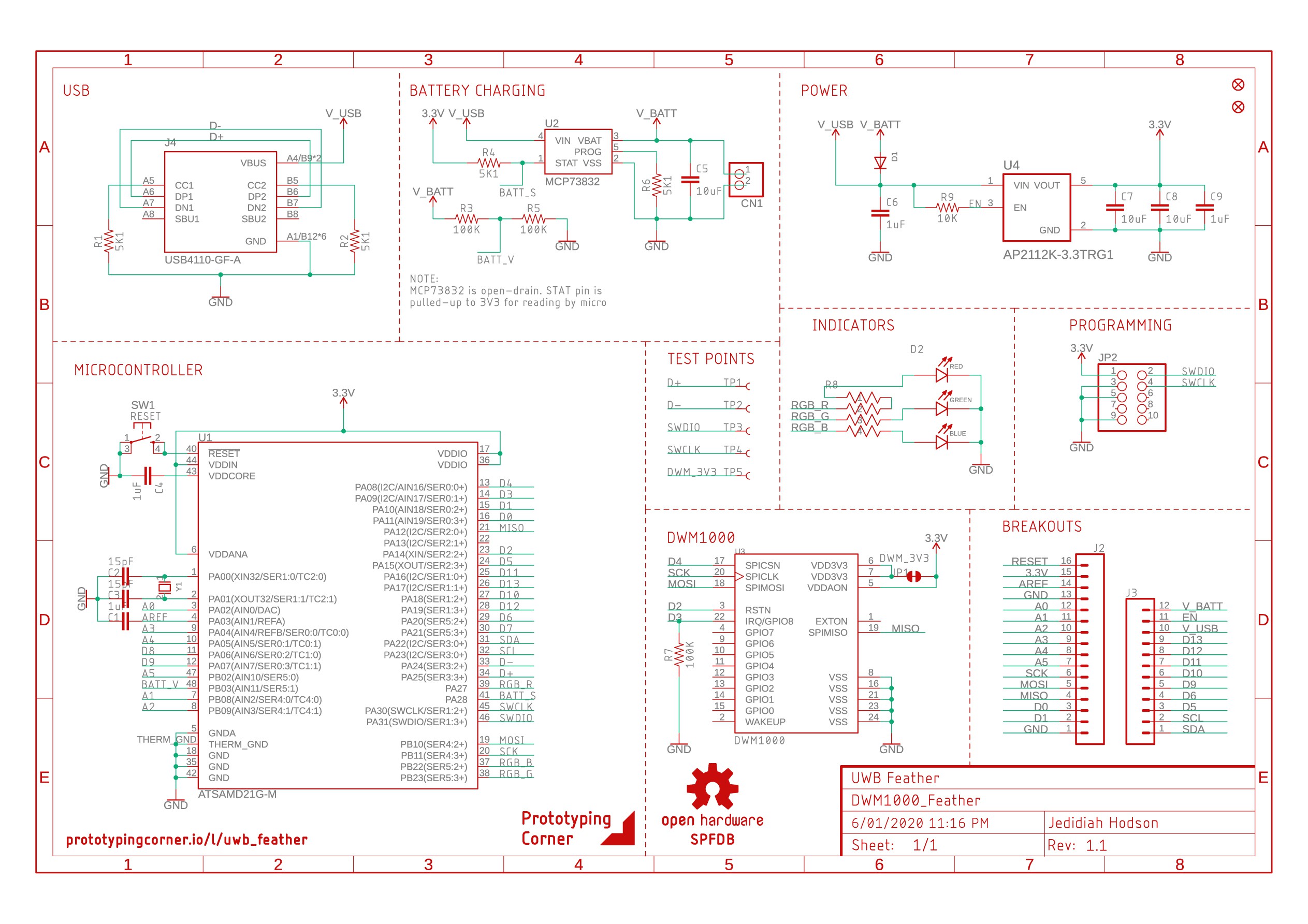
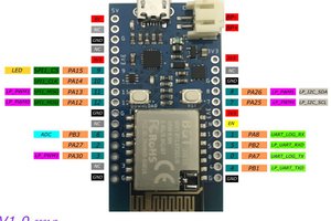
As mentioned in the introduction, the UWB Feather consists of an ATSAMD21 ARM Cortext M0+ for the brains and a Decawave DWM1000 module for the ultra-wide band wireless, in the feather form-factor. The design is relatively simple consisting of 20 BoM items on a 2-layer PCB. Pinout is Adafruit M0 Feather compatible
LiPo charging is handled by the MCP73831 single-cell, fully integrated charge management controller. Battery voltage can be monitored on D9, however is access to all the IO is required, JP1 can be cut to free up this pin. 3.3 volt regulation is preformed by the AP2112K-3.3 low dropout linear regulator, providing up to 600mA.
Pinout is fully compatible with the Adafruit M0 feather line for easy code portability. The DWM1000 IO lines are connected to the SPI bus and digital pins 2, 3 & 4 for RST, IRQ & SPI_CS respectivly (which are not exposed via the header). D13 is also connected to the onboard LED, as is standard among many Arduino-compatible boards.
Programming can be preformed over the SWD header or via USB if loaded with a corresponding bootloader such as the uf2-samdx1 from Microsoft. See firmware for more.

Note on V1.0: There is an issue with the USB-C connector on version 1 of this board. The footprint I used did not include the cutout required for the cutout mounting method of this component.
Version 1.1 will include a fix for this as well as adding a micro-b connector for those who want it. See version 1.1 considerations below.
The DWM1000 has a One Time Programmable (OTP) user programmable memory for storing calibration information (see 1.6 in the datasheet). To program this region the VDD3V3 pins may need to be raised to 3.8 volts temporarily. To do this JP2 can be cut and a separate power supply can be connected to selectively boost the power to the module.
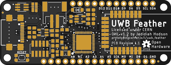
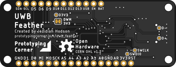
Version 1 Board Renders


Bill of Materials
BoM items are all available from DigiKey and are plentiful in supply. Total BoM cost was $60 AUD for 1 quantity, however further optimization can shave a few dollars off this.
CSV version of this table can be found in the project repository.
| Manufacturer Part Number | Manufacturer | Digi-Key Part Number | Customer Reference | Quantity | Description |
|---|---|---|---|---|---|
| DX07B024JJ3R1600 | JAE Electronics | 670-2963-1-ND | J1 | 1 | CONN RCP USB3.1 TYPEC 24P SMD RA |
| S2B-PH-SM4-TB(LF)(SN) | JST Sales America Inc. | 455-1749-1-ND | CN1 | 1 | CONN HEADER SMD R/A 2POS 2MM |
| KMR241GLFS | C&K | 401-1431-1-ND | SW1 | 1 | SWITCH TACTILE SPST-NO 0.05A 32V |
| AP2112K-3.3TRG1 | Diodes Incorporated | AP2112K-3.3TRG1DICT-ND | U4 | 1 | IC REG LINEAR 3.3V 600MA SOT25 |
| MBR120VLSFT1G | ON Semiconductor | MBR120VLSFT1GOSCT-ND | D2 | 1 | DIODE SCHOTTKY 20V 1A SOD123FL |
| ATSAMD21G18A-MU | Microchip Technology | ATSAMD21G18A-MU-ND | U1 | 1 | IC MCU 32BIT 256KB FLASH 48QFN |
| 20021221-00010C4LF | Amphenol ICC (FCI) | 609-3700-1-ND | J4 | 1 | CONN HEADER SMD 10POS 1.27MM |
| DWM1000 | Decawave Limited | 1479-1002-1-ND | U3 | 1 | RF TXRX MODULE 802.15.4 CHIP ANT |
| MCP73831T-2ATI/OT | Microchip Technology | MCP73831T-2ATI/OTCT-ND | U2 | 1 | IC CONTROLLR LI-ION 4.2V SOT23-5 |
| RC0603FR-075K1L | Yageo | 311-5.10KHRCT-ND | R1, R2, R6 | 3 | RES SMD 5.1K OHM 1% 1/10W 0603 |
| SML-D12D8WT86 | Rohm Semiconductor | 511-1577-1-ND | D1 | 1 | LED ORANGE DIFFUSED 0603 SMD |
| 150060BS55040 | Würth Elektronik | 732-12013-1-ND | D5 | 1 | LED BLUE DIFFUSED 0603 SMD |
| RC0603FR-071KL | Yageo | 311-1.00KHRCT-ND | R4 | 1 | RES SMD 1K OHM 1% 1/10W 0603 |
| RC0603FR-07100KL | Yageo | 311-100KHRCT-ND | R5, R3 | 2 | RES SMD 100K OHM 1% 1/10W 0603 |
| TMCJ0J106MTRF | Vishay Sprague | 718-2355-1-ND | C5, C7, C8 | 3 | CAP TANT 10UF 20% 6.3V 0603 |
| RC0603FR-0710KL | Yageo | 311-10.0KHRCT-ND | R10 | 1 | RES SMD 10K OHM 1% 1/10W 0603 |
| TMCJ1C105MTRF | Vishay Sprague | 718-2362-1-ND | C1, C4, C6, C9 | 4 | CAP TANT 1UF 20% 16V 0603 |
| RC0603FR-07330RL | Yageo | 311-330HRCT-ND | R9 | 1 | RES SMD 330 OHM 1% 1/10W 0603 |
| CC0402FRNPO9BN150 | Yageo | 311-1642-1-ND | C2, C3 | 2 | CAP CER 15PF 50V C0G/NPO 0402 |
| FC-135 32.7680KA-A0 | EPSON | SER4077CT-ND | Y1 | 1 | CRYSTAL 32.7680KHZ 12.5PF SMT |
Hardware Version 1.1 Considerations
There are a number of changes required for a board that would be put into production as nobody gets it right the first time,...
Read more »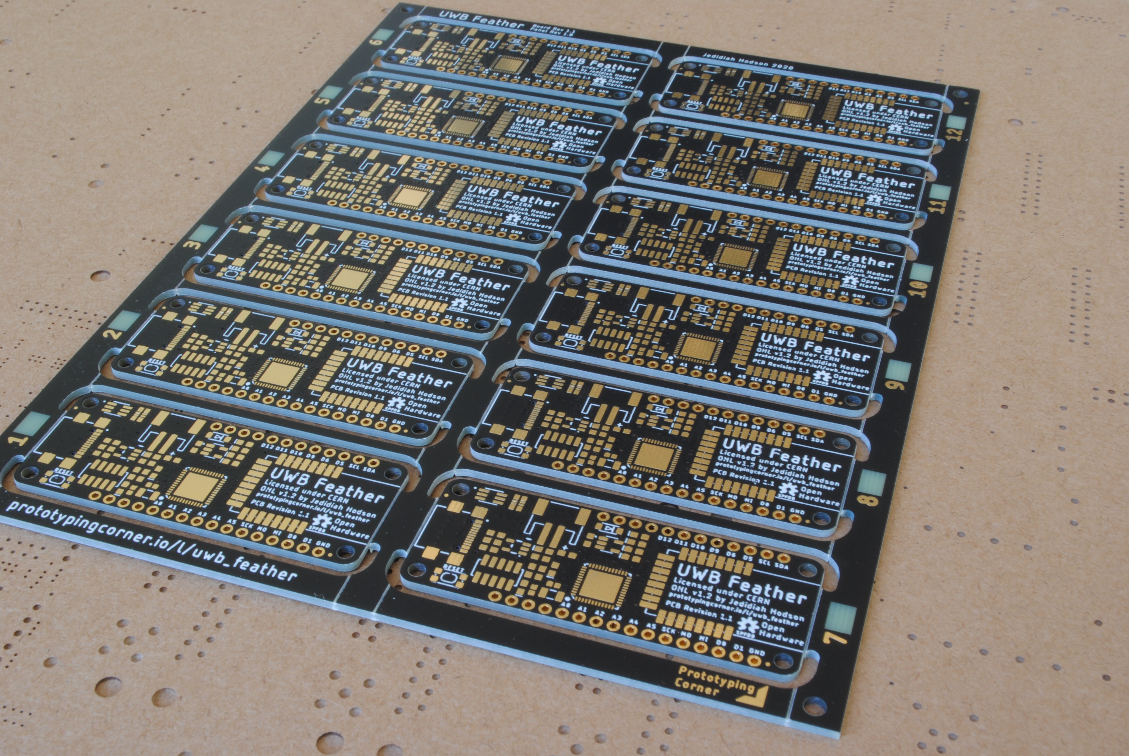

 SimonXi
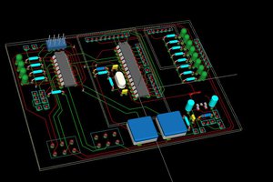
 Michael O'Toole
 Bruce Land
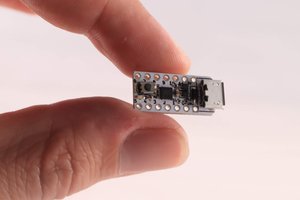
 Sander van de Bor