 bobgreenwade
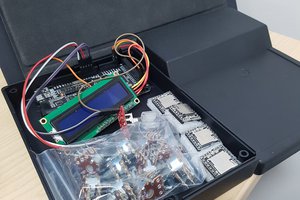
The FV-1 Reverb IC from Spin Semiconductor was designed to add reverb effects to any audio system, from electric guitar amplifiers to karaoke machines to car audio. By applying it to a FeatherWing, these effects can be put into a very compact application, such as a voice changer, portable instrument mike, or pocket stereo.
While the chip's title only refers to reverb, and the board's name (EchoWing) follows that pattern, the chip is actually capable of a good deal more; its internal programs have features such as changing pitch up to 4 semitones, adding tremolo and/or flange, and filtering high and low frequencies. It can only handle three functions at a time, but it can do them.
(It actually would be more accurate to say that it can handle three variables at a time; more than one variable can affect any function, and the chip can have functions that only used fixed values. Thinking of those three variables as "functions" just makes things easier to visualize.)
While this is intended for use in conjunction with the SoundWing, I do expect that other users can find many other uses for it. (Makers are, by definition, a pretty creative bunch!)
Please note that corrections, suggestions, and any other constructive criticism is always welcome -- including offers of practical help!
Channel Info:
The dozen I/O ports on the FV-1 are handled with a Maxim Semiconductor MAX11312. While that chip can be configured to any of 8 I2C ports (using its A0 and A1 pins), four of those involve hooking up the A0 pin to either SCL or SDA, which would be just a little difficult using solder jumpers. So, besides the default address of 0111000, the chip on this board can be changed to 0111100, 0111011, or 0111111 (A1 controls the fourth digit, and A0 controls the last two together; the solder jumpers are marked "4" and "3" respectively). This still allows up to four of these boards in one project, for an even dozen effects parameters; it's unlikely that anyone would need more than two, but at least the possibility exists.
The port assignments are:
- Port 0: Left-channel In
- Port 1: Right-channel In
- Port 2: Clip LED
- Port 3: Internal/External Program select
- Port 4: Program select LSB
- Port 5: Program select
- Port 6: Program select MSB
- Port 7: Pot 0
- Port 8: Pot 1
- Port 9: Pot 2
- Port 10: Left-channel out
- Port 11: Right-channel out
The "Pot" (potentiometer) pins control the three characteristics chosen by the current Program.
Programming:
There are two programming matters for this board: programming the MAX11312 configuration, and putting any additional presets on the EEPROM. (For now, this section is mostly just a long-term placeholder to remind me that these need to be written out and posted, and a notepad for what I've figured out so far. Once I'm confident that the code all works like it's supposed to, I'll make it all downloadable in the Files section.)
This code is a work in progress; currently it's just notes showing the parameter name from the data sheet, the value assigned, and what that value represents.
ADCCTL     : 3 [ADCs in continuous sweep mode]
DACCTL     : 1 [DACs in immediate upgrade mode]
ADCCONV    : 3 [ADC conversion rate is 400 ksps]
DACREF     : 0 [DAC uses external reference]
TMPCTL     : 0 [all temperature monitors disabled]

FUNCPRM_0  : 800
FUNCPRM_1  : 800
FUNCPRM_7  : 800
FUNCPRM_8  : 800
FUNCPRM_9  : 800 [all DACs set to -5 to +5V]
FUNCPRM_10 : 860
FUNCPRM_11 : 860 [both ADCs set to 0 to 2.5V, 8 samples]

FUNCID_0   : 5
FUNCID_1   : 5 [DAC]
FUNCID_2   : 1 [GPI]
FUNCID_3   : 3
FUNCID_4   : 3
FUNCID_5   : 3
FUNCID_6   : 3 [GPO]
FUNCID_7   : 5
FUNCID_8   : 5
FUNCID_9   : 5 [DAC]
FUNCID_10  : 7
FUNCID_11  : 7 [ADC]
Of course the numbers in the first two blocks may be subject to change, based on the performance of the device once I'm able to test it.
I don't yet have anything worked out for the EEPROM (though see the final paragraph below).
Links:
Spin Semiconductor FV-1 data sheet
Future plans:
Once I have a physical...
Read more »

 Craig Hissett
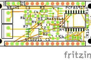

 Jonathan Brodsky
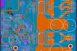
It's nice to see another person using Fritzing. By the way, if you hold down the ctrl key while moving a trace, it will snap to angles in 45° increments, which makes it easier to keep it all clean.