Close
0%
0%

electrical energy monitor

a simple approach to home energy monitoring (with smart home integration)

Similar projects worth following
I tried to keep the hardware design as simple as possible.

Three current transformers (one per phase) output 0...1V corresponding to 0...30A.
The 0...1V signal gets measured by an ADS1115 analog to digital converter.
The modules are connected via I2C to an Arduino with an ethernet extension.

A routine on the Arduino calculates the real power (with an approx. cos phi 0.9) and sends the data to my smart home (via ModbusTCP).


The goal of this project is not to measure the exact amount of energy being consumed. So I pass on measuring the voltage of each phase and calculating the exact cos phi (power factor). Instead, I set the voltage to 230V and the cos phi to 0.9.  

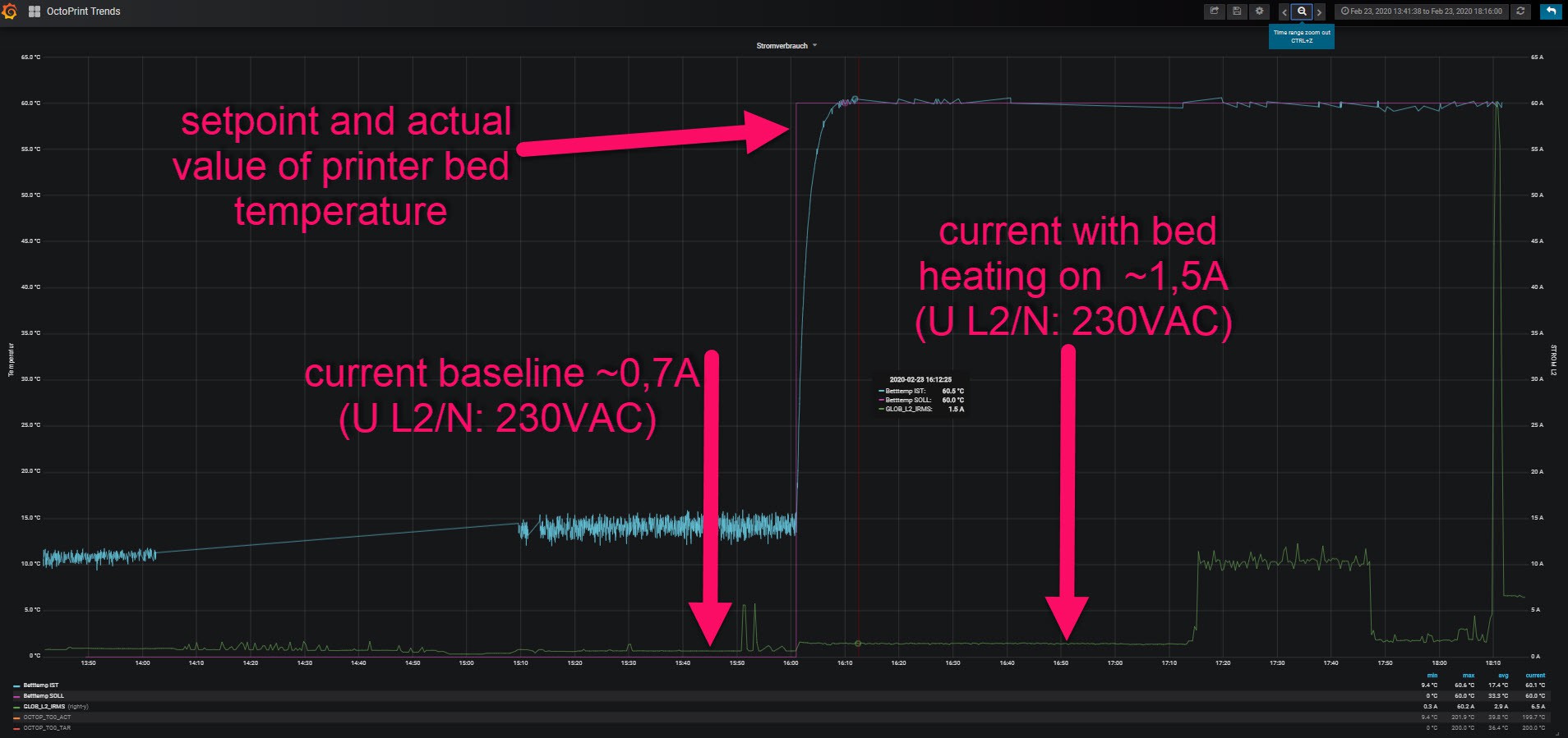
So far it works better than expected. It is easily possible to identify individual appliances:

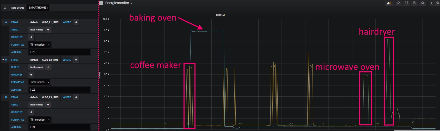
See project logs for more details...

  • Update: current on L2 (Phase 2)

    stefan.schnitzer02/24/2020 at 13:08 0 comments

    The current meter is sensitive enough to detect the current rise of my 3D-printer's bed heater:

  • a new case and a lesson that I should spend more time on slicer settings

    stefan.schnitzer01/03/2020 at 07:03 1 comment

    I designed and printed a new case... 

    ...with mount brackets for the DIN-rail and some ventilation grilles.

    It came out useable but some details got lost.  (4h @0.32mm layer height with an 0.4mm nozzle)

    In the future, I should set the focus on print quality instead of short print times. 

  • field test

    stefan.schnitzer12/31/2019 at 18:07 0 comments

    Now it's time for the first field test. I assembled the 3d-printed case (with some tape) and installed the current transformers in my mains input.  (Fortunately, there were 4 free wires on a cat cable that brings DSL to my modem/router)

    After that, I was able to check the values transmitted to the smart home with a clamp amp meter.

    -> field test passed -> design and 3d print a better case (with DIN-rail mounting brackets)... 

  • assembly and first test

    stefan.schnitzer12/31/2019 at 00:26 0 comments

    I soldered the three analog to digital converter on a perfboard and connected it to 5V, GND and the I2C interface. After that, I added three 3,5mm jack sockets (which I harvested from an old PCI sound card). The three jack sockets are connected with the A0 input of the ADCs.   

    For the first test, I connected a test load and a reference measuring device through all three current transformers.

    All three inputs (later used for L1, L2, L3) showed nearly the same value and an acceptable deviation to the reference energy meter.  -> first test passed -> design and 3d print a simple case... 

    You must be very cautious and work safely with mains voltage! 

    See this great article about working safely: 
    https://hackaday.com/2016/05/11/looking-mains-voltage-in-the-eye-and-surviving-part-1/

View all 4 project logs

Enjoy this project?

Share

Discussions

scarletwiz wrote 09/23/2022 at 07:22 point

This is Scarlet from WIZnet team. We are developing various Ethernet solutions. 

could you share this project code to everyone? It so great project, so it will be help to many people.
If you have any questions or inquiries when you sre using Wiznet Ethernet solutions, please contact us at the email below. (maker@wiznet.io)

  Are you sure? yes | no

stefan.schnitzer wrote 09/29/2022 at 13:46 point

I will post the source code as soon I am able to find the file in my NAS. Unfortunately, my backup routines were not very good when creating this project.

  Are you sure? yes | no

scarletwiz wrote 09/30/2022 at 00:16 point

I'm sorry I can't see the code. I'll wait for the code to come out one day. and our team and I are looking forward to your next project. Thank you for the using WIZnet product

  Are you sure? yes | no

bb wrote 07/12/2021 at 18:05 point

It cool project. Can you publish about this project to Github?

  Are you sure? yes | no

stefan.schnitzer wrote 09/29/2022 at 13:47 point

I will post the source code ( here ) as soon I am able to find the file in my NAS. Unfortunately, my backup routines were not very good when creating this project.

  Are you sure? yes | no

Similar Projects

Does this project spark your interest?

Become a member to follow this project and never miss any updates