 stefan.schnitzer
I soldered the three analog to digital converter on a perfboard and connected it to 5V, GND and the I2C interface. After that, I added three 3,5mm jack sockets (which I harvested from an old PCI sound card). The three jack sockets are connected with the A0 input of the ADCs.
For the first test, I connected a test load and a reference measuring device through all three current transformers.
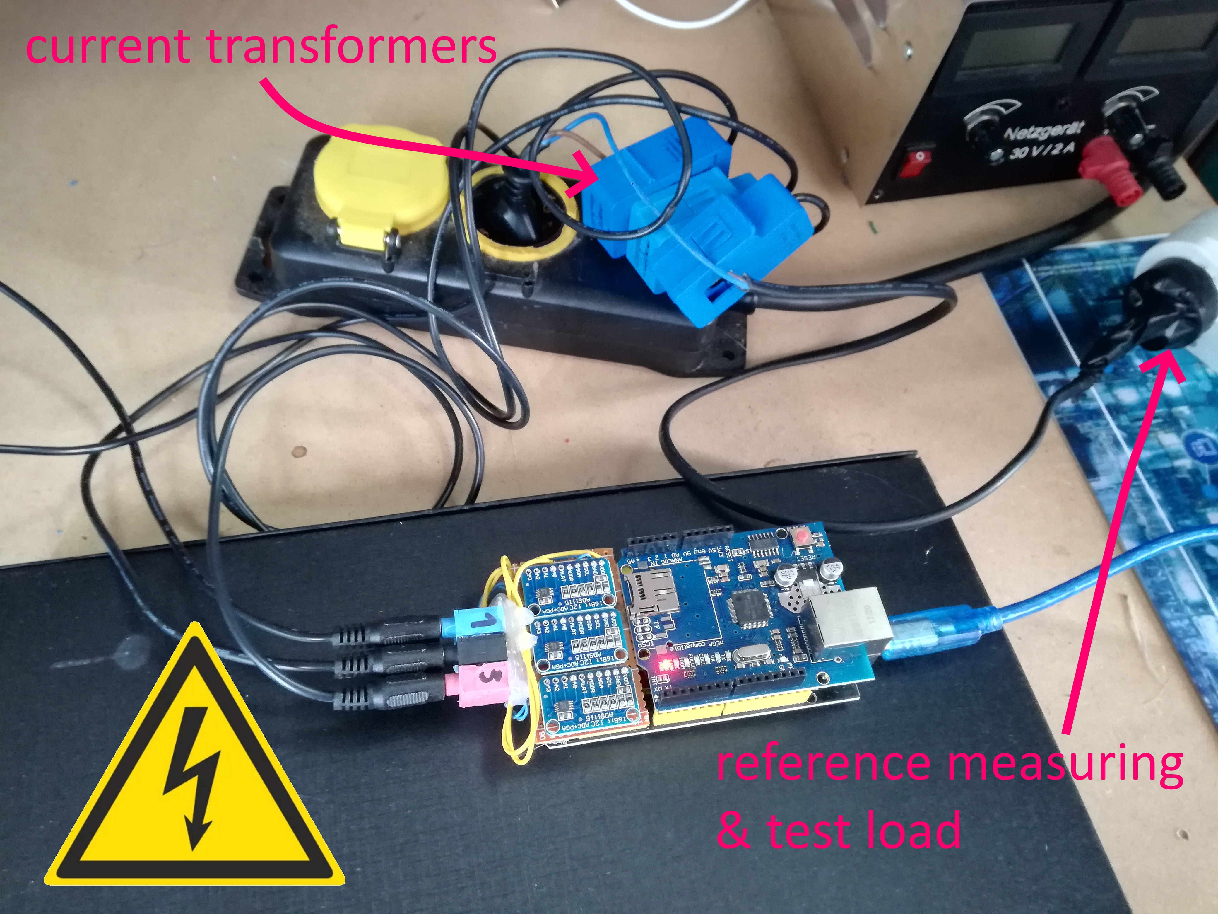
All three inputs (later used for L1, L2, L3) showed nearly the same value and an acceptable deviation to the reference energy meter. -> first test passed -> design and 3d print a simple case...
You must be very cautious and work safely with mains voltage!
See this great article about working safely:
https://hackaday.com/2016/05/11/looking-mains-voltage-in-the-eye-and-surviving-part-1/
Discussions
Become a Hackaday.io Member
Create an account to leave a comment. Already have an account? Log In.