stefan.schnitzer
-
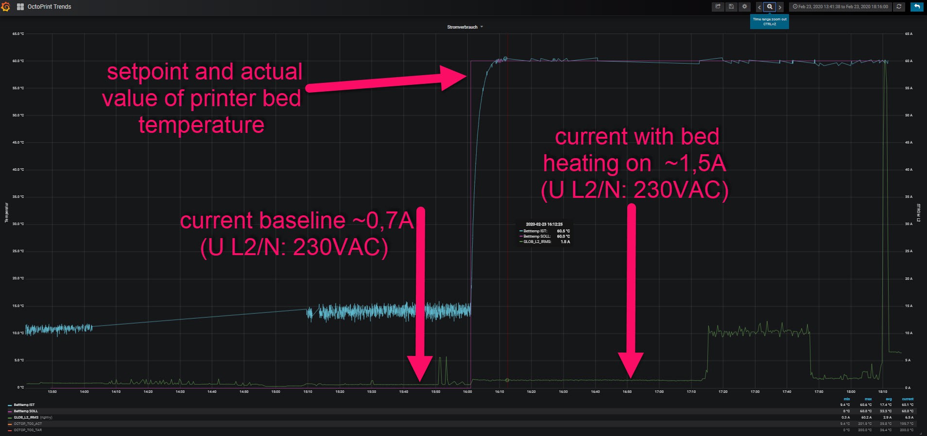
Update: current on L2 (Phase 2)
02/24/2020 at 13:08 • 0 commentsThe current meter is sensitive enough to detect the current rise of my 3D-printer's bed heater:
![]()
-
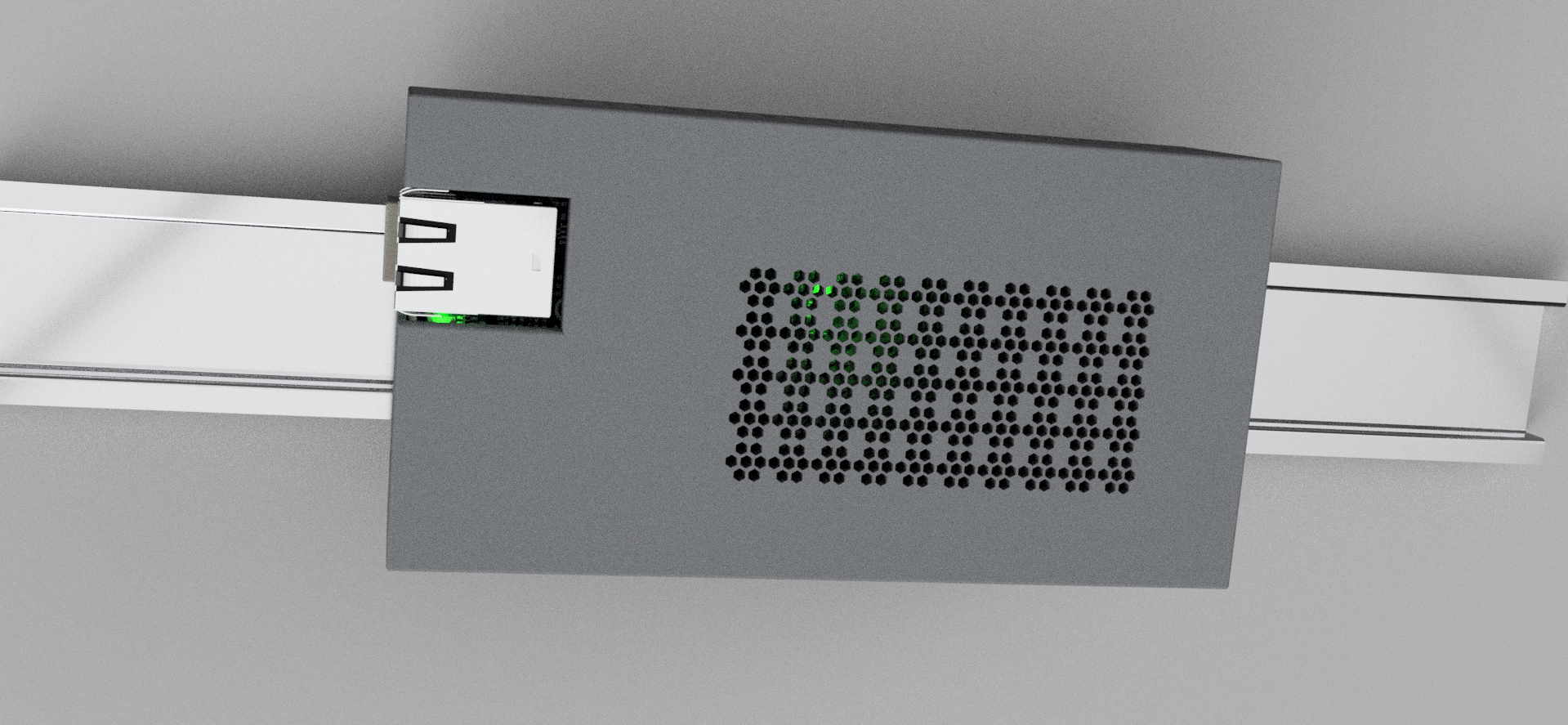
a new case and a lesson that I should spend more time on slicer settings
01/03/2020 at 07:03 • 1 commentI designed and printed a new case...
![]()
...with mount brackets for the DIN-rail and some ventilation grilles.
![]()
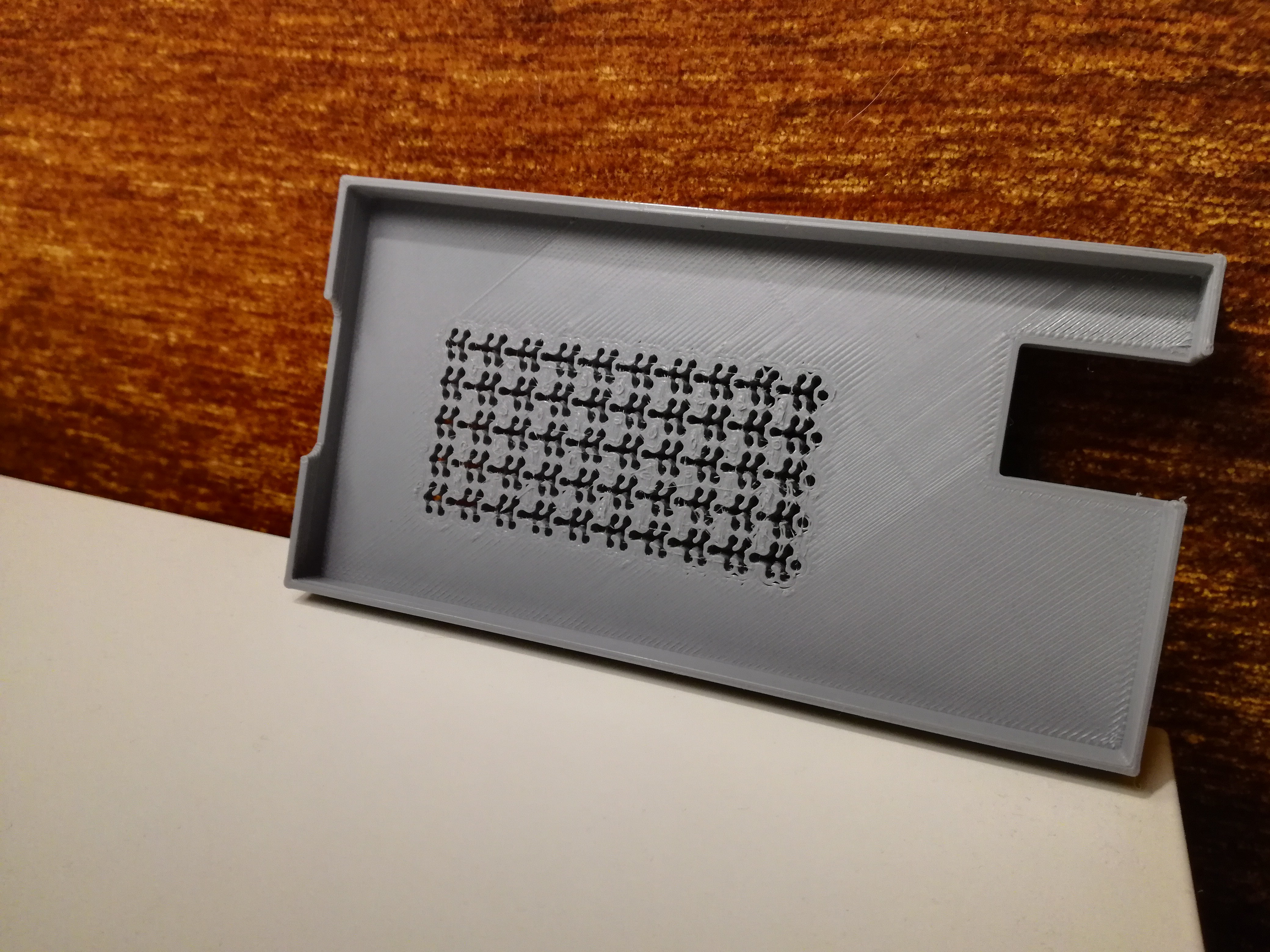
It came out useable but some details got lost. (4h @0.32mm layer height with an 0.4mm nozzle)
![]()
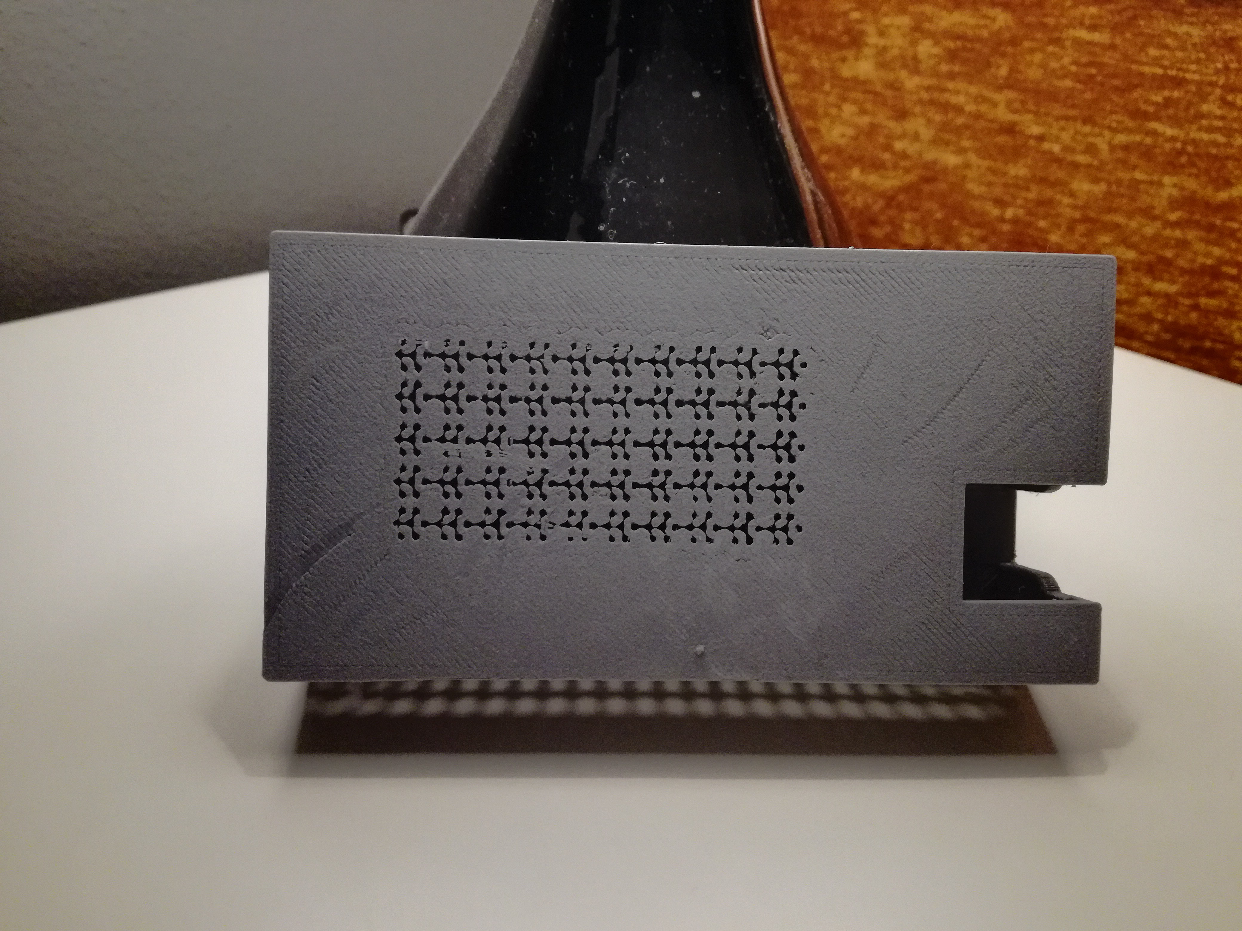
In the future, I should set the focus on print quality instead of short print times.
![]()
-
field test
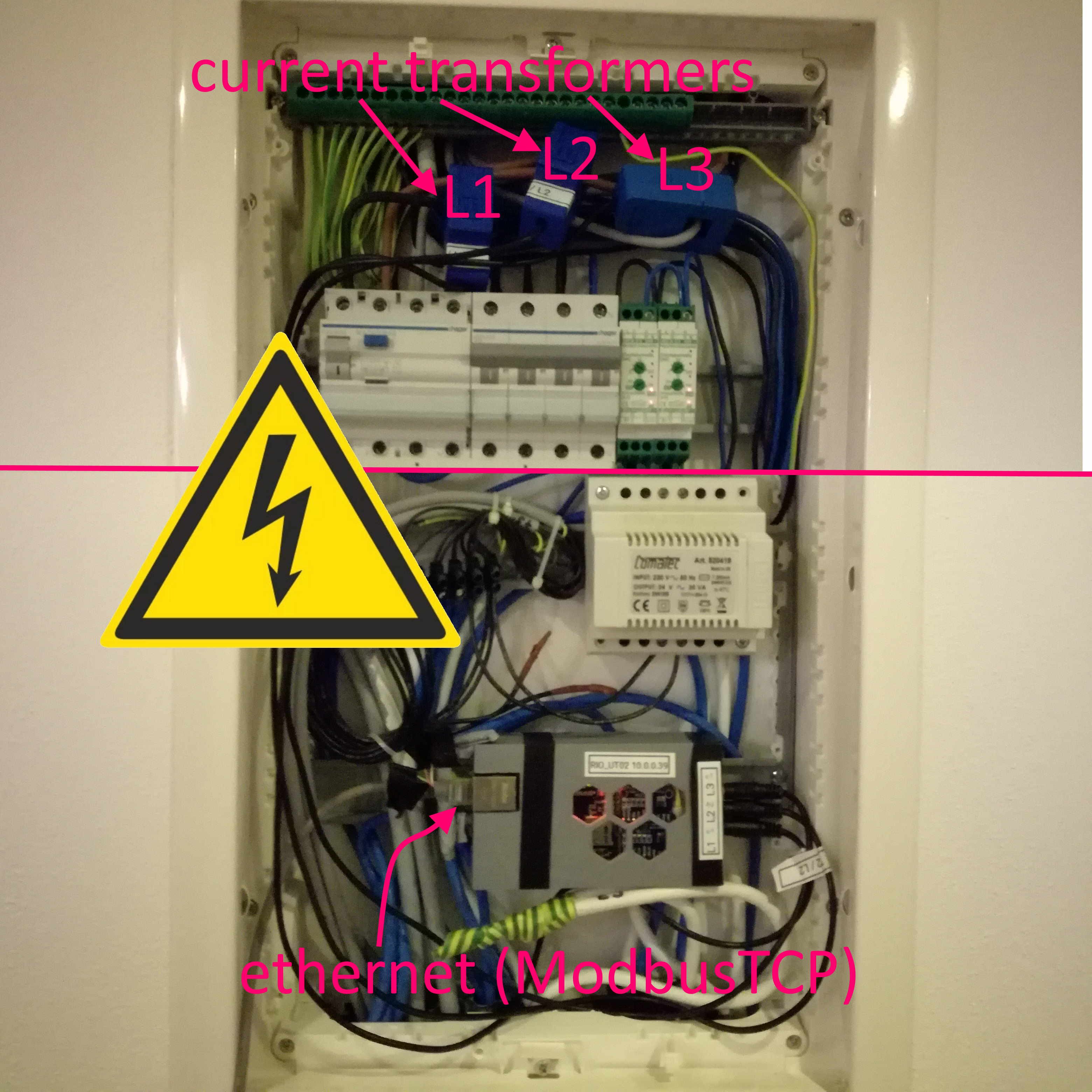
12/31/2019 at 18:07 • 0 commentsNow it's time for the first field test. I assembled the 3d-printed case (with some tape) and installed the current transformers in my mains input. (Fortunately, there were 4 free wires on a cat cable that brings DSL to my modem/router)
![]()
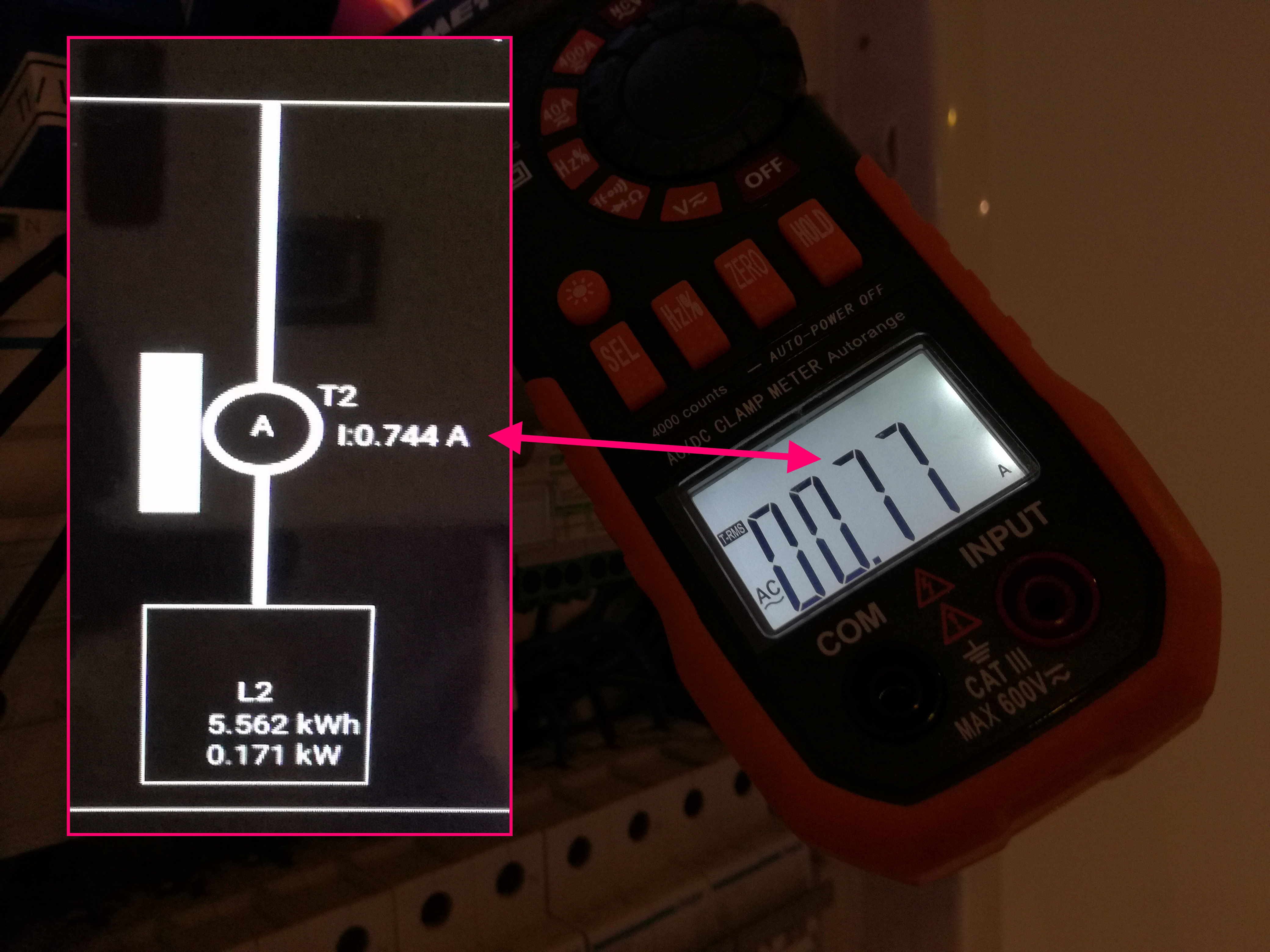
After that, I was able to check the values transmitted to the smart home with a clamp amp meter.
![]()
-> field test passed -> design and 3d print a better case (with DIN-rail mounting brackets)...
-
assembly and first test
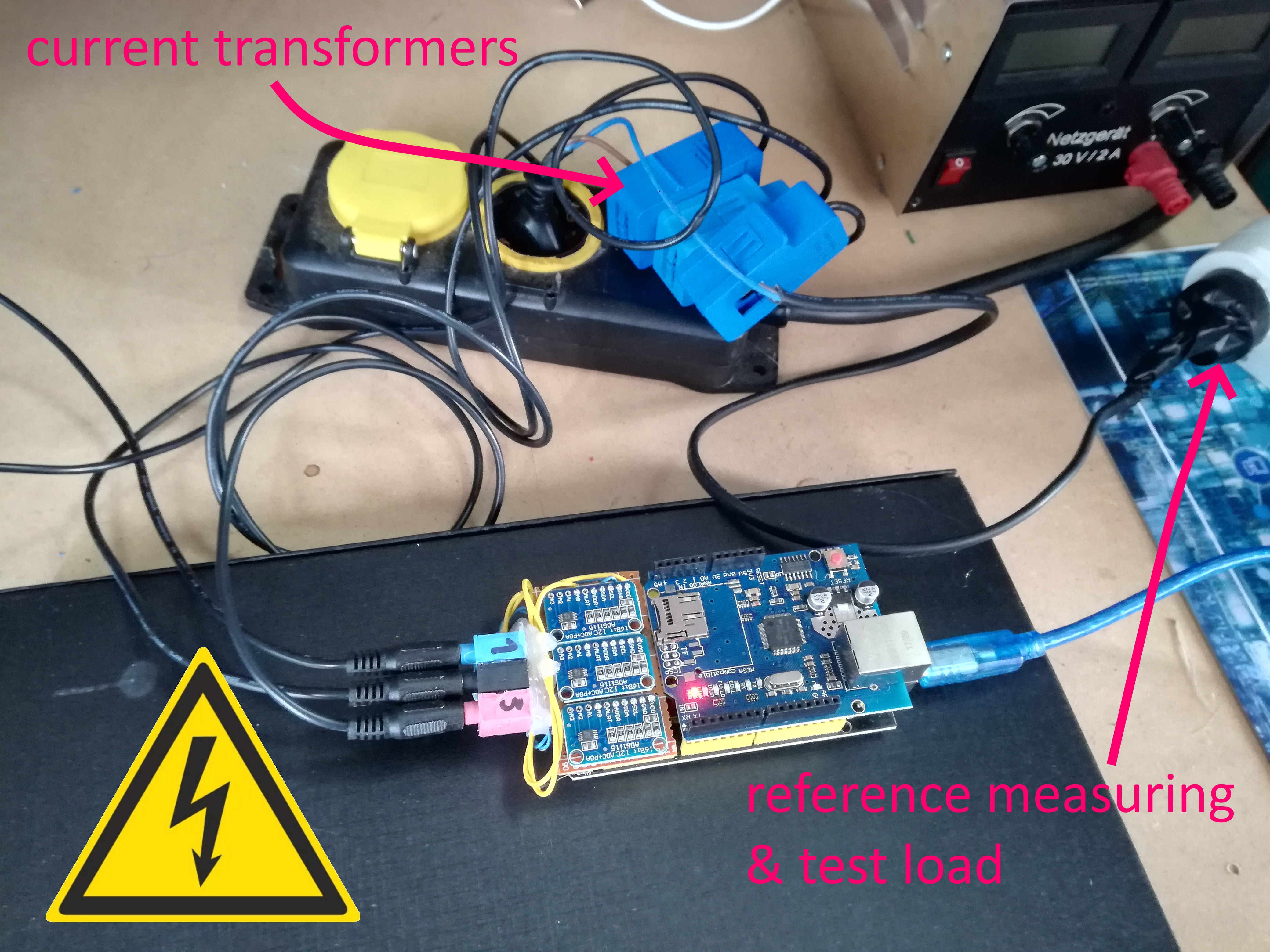
12/31/2019 at 00:26 • 0 commentsI soldered the three analog to digital converter on a perfboard and connected it to 5V, GND and the I2C interface. After that, I added three 3,5mm jack sockets (which I harvested from an old PCI sound card). The three jack sockets are connected with the A0 input of the ADCs.
For the first test, I connected a test load and a reference measuring device through all three current transformers.
![]()
All three inputs (later used for L1, L2, L3) showed nearly the same value and an acceptable deviation to the reference energy meter. -> first test passed -> design and 3d print a simple case...
You must be very cautious and work safely with mains voltage!
See this great article about working safely:
https://hackaday.com/2016/05/11/looking-mains-voltage-in-the-eye-and-surviving-part-1/
electrical energy monitor
a simple approach to home energy monitoring (with smart home integration)