 Jithin Sanal
Introduction
Hey guys, I am back with another cool Robot chassis from BangGood. Hope you have gone through our previous projects – Spinel Crux V1 – The Gesture Controlled Robot, Spinel Crux L2 – Arduino Pick and Place Robot with Robotic Arms and The Badland Brawler which we published last month. Looks cool with under glowing lights right?
This time I have a rough Terrain Robot with 4 Wheel Drive and dedicated suspension for it to travel over rough terrain. Check it out.
Why not build one for yourself? Here we will learn how to build a Off Road Wireless Multipurpose 4 Wheel Drive Arduino Tracked Robot for a smooth ride over rough terrain – A DIY Rough Terrain Wireless Crawler with Suspension.
We will provide you with the design, code, circuit diagrams and links to buy your own robot kit, chassis and the sensor modules used in this project.
Online PCB Manufacturer – JLCPCB
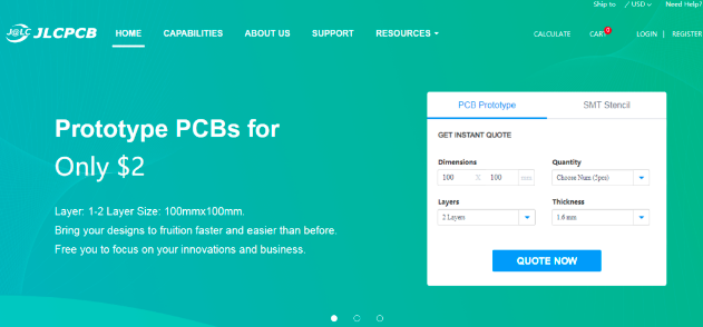
JLCPCB is one of the best Online PCB manufacturing company from where you can order PCBs online without any hassle. The company works 24 hours a day, 7 days a week nonstop. With their high tech machinery and automated work stream, they can manufacture huge quantities of high-class PCBs within hours.
JLCPCB can develop PCBs of various complexity. They develop Simple and cheap PCBs with Single layer board for hobbyists and enthusiasts as well as complex multi layer board for high standard industrial applications. JLC works with large product manufacturers and may be the PCB of devices you are using such as laptop or mobile phones were made at this factory.
HC12
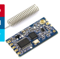
HC 12 is a really cheap long range wireless module which can be used for wireless serial communication over a long distance of upto 1.7 KM. The module is really compact light weight and breadboard friendly which makes this the best wireless controller for our project.
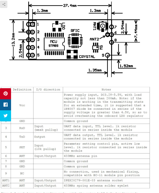
Pinout
Testing HC12 Connection
#include <SoftwareSerial.h>
SoftwareSerial HC12(10, 11); // HC-12 TX Pin, HC-12 RX Pin
void setup() {
Serial.begin(9600); // Serial port to computer
HC12.begin(9600); // Serial port to HC12
}
void loop() {
while (HC12.available()) { // If HC-12 has data
Serial.write(HC12.read()); // Send the data to Serial monitor
}
while (Serial.available()) { // If Serial monitor has data
HC12.write(Serial.read()); // Send that data to HC-12
}
}
Joystick
This is the most widely used robotic controller which comes with various robot DIY robot kit/robot arm kit that is built to work with arduino. The design is quite simple and is very easy to use. It uses two potentiometers to calculate the motion in the x axis and y axis and a switch to sense the button press.
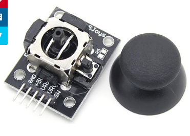
This can be easily connected to the arduino’s analog pins and read analog values directly.
Code for testing the joystick is available down below. Feel free to download/edit it as per your need.
Before uploading the main code, make sure your joystick works by using this code. Download the code from the above link. In this example, what we are doing is simply collecting the data analog outputs from the Joystick using the analog pins (A0, A1,A2) of arduino. These values are stored in the variables and are later printed on the serial monitor
Arduino Pro Mini
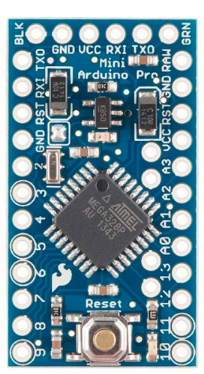
This teeny tiny board was developed for applications and projects where space is premium and installations made permanent.
Small, available in 3.3 V and 5 V versions, powered by ATmega328. Due to its small size, in this project we will be using this board to control Arduino Based Motor Driver Board.
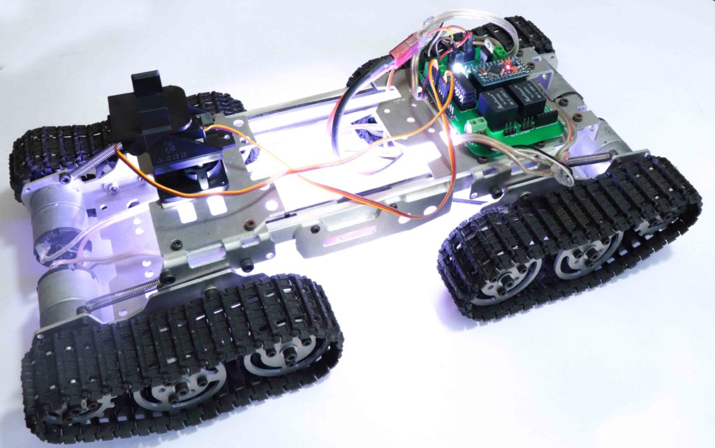
The Robot Chassis
This is the robot chassis I used to make my BLE Robot. I got this kit banggood.com. Not only this one, they have so many types of robot frames, motors and almost all the sensors for doing arduino, raspberry pi and other electronics and hobby projects.
You will get all these things for a cheap price with really fast and quality shipping.
And the great thing about this kit is they provide all the tools you need to assemble the frame together.
We will divide this tutorial into 2 Parts – The Remote Controller and The Robot
1- The Remote Controller
The Transmitter consist of a breadboard in which we mount all the sensors and components to get the data which is used to drive the Off-Road Wireless Surveillance 6 Wheel Drive Robot. This includes an accelerometer, a joystick and an HC12 module.
We will use the accelerometer as well as the joystick to control the off-road robot. For now, we will use the joystick button to close the robotic hand. The data from these sensors are transmitted wirelessly to the DIY robot using an HC12 module.
In the previous post, I showed you how you can make a remote controller using HC12 Wireless Module, Joystick and Accelerometer. We can use the same remote for this project also. Click here to know more about the HC12 Remote Controller.
Arduino Motor Shield Board Explained
Features of Pro Mini Motor Shield PCB

- Controls 2 Motors Independently at a time
- Independent Speed Control using PWM
- Compact Design
- 5 V, 12 V and Gnd Headers for extra components
- Increase Power by Piggybacking
- Support HC12 Wireless Module
Now let us take a look at the circuit of our motor driver board.Looks a bit messy? Don’t worry, I will explain it for you.
The Regulator
The input power is connected to a 7805 regulator. 7805 is a 5V regulator which will convert an input voltage of 7- 32V to a steady 5V DC supply. 5 V supply is connected to voltage input of Arduino as well as for Logical operations of L293D IC. There are indicator LEDs across 12V and 5V terminals for easy troubleshooting.
So, you can connect an input voltage of anywhere between 7V to 32 to this circuit. For my bot, I prefer a 11.1V Lipo Battery.
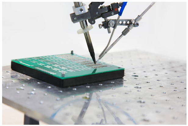
Make Your Own Arduino Motor Shield PCB
Now let me tell You How I designed the circuit and got this PCB done from JLCPCB.
Step 1 – Creating the prototype
First connect all the components together on the breadboard so that I can troubleshoot easily if something goes wrong. Once I got everything working properly, I tried it on a Robot and played with it for some time. That time, I made sure that the Circuit is working properly and is not heating up.
Step 2 – The Schematics
To draw circuits and design PCBs, we have online PCB designing tools from EasyEDA, provides all the necessary capability for online PCB Design and PCB Printing of Circuit Boards with hundreds of components and multiple layers with thousands of tracks.I drew a circuit in EasyEDA which included all the components on the breadboard – the ICs, Arduino Nano and HC12 module which are connected to the digital pin of the Arduino. I have also added some headers which are connected to Analog Pins and Digital Pins of These buttons will be useful in the future.
Connections
Also, there are 5V, 12V, Gnd, wireless module, digital and analog pin headers incase you want to add sensors and take readings in the future. Complete pin mapping is explained in below sections.
Motor Driver 1 Enable 1 – A0 InM1A – 2 InM1B – 3
Enable 2 – 8 InM2A – 7 InM2B – 4
HC12 Vin – 5V Gnd – Gnd Tx/Rx – D10 Tx/Rx – D11
Relay
Relay 1 – 12 Relay 2 – 13
I also added a 7805, regulator which will helped me to provide an input voltage between 7 volt and 35 volt in the input, so that I can use a 7 volt power supply, 9-volt battery or even a 12 volt lithium polymer battery without any issues.
Step 3 – Creating PCB Layout
Next, designing the PCB. PCB Layout is actually a significant part of PCB Design, we use PCB Layouts to make PCBs from schematics. I designed a PCB where I could solder all the components together.
For that, first save the schematics and from the top tool list, Click on the convert button and Select “Convert to PCB”.
This will open up a window. Here, you can place the components inside the boundary and arrange them the way you want. The easy way route all the component is “auto-route” process. For that, Click on the “Route” Tool and Select “Auto Router”.
This will open up an Auto Router Config Page where you can provide details such as clearance, track width, layer information etc. Once you have done that, click on “Run”.

Here is the link to EasyEDA Schematics and Gerber Files of L293D Arduino Motor Shield Board . Please feel free to download or edit the schematics/PCB layout.
That’s it guys, your layout is now complete. This a dual layer PCB which means the routing is there in both side of the PCB. You can now download the Gerber file and use it to manufacture your PCB from JLCPCB.
Step 4 – Getting High Quality PCB Manufactured
JLCPCB is a PCB manufacturing company with a full production cycle. Which means they start from “A” and finishes with “Z” of PCB manufacturing process. From raw materials to finished products, everything is done right under the roof.
Go to JLCPCBs website and create a free account. Once you have successfully created an account, Click on “Quote Now” and upload your Gerber File.

Gerber File contains information about your PCB such as PCB layout information, Layer information, spacing information, tracks to name a few.
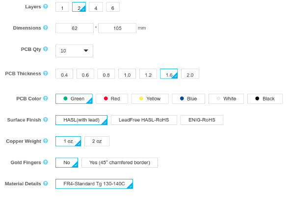
Below the PCB preview, you will see so many options such as PCB Quantity, Texture, Thickness, Color etc. Choose all that are necessary for you.
Once everything is done, click on “Save To Cart”. In the next page, you can choose a shipping and payment option and Check Out Securely. You can either use Paypal or Credit/Debit Card to pay.
Thats it guys. Its Done. The PCB will be manufactured and shipped with in days and will be delivered to your doorstep within the mentioned time period.


Once you get the PCB in hand, all you have to do is solder the header pins and all other components.

Once it is done, connect the power adapter and you will see LED1 will glow up. This means it is working.

Now your bot is ready for some action, why not take it out for a ride?