 Space Buck
Current status of the Double-Oh: I assembled two of the version 3.0 PCB, and they both reboot themselves whenever I try to set the adjustable voltage above 1.8V or so. In addition, the ESP32-PICO-V3 feels like it's getting a lot hotter than the ESP32-PICO-D4 did, but I don't have any measurements to back that up yet. It may be that my firmware needs to be optimized for performance (it does; I should at least be using an async webserver).
So, it's pretty hard to hook up the Double-Oh to an ammeter or an oscilloscope while it's inside a battery compartment somewhere. Something I should have done a long time ago is to build an easy tool to collect key measurements. I'm finally making good on that.
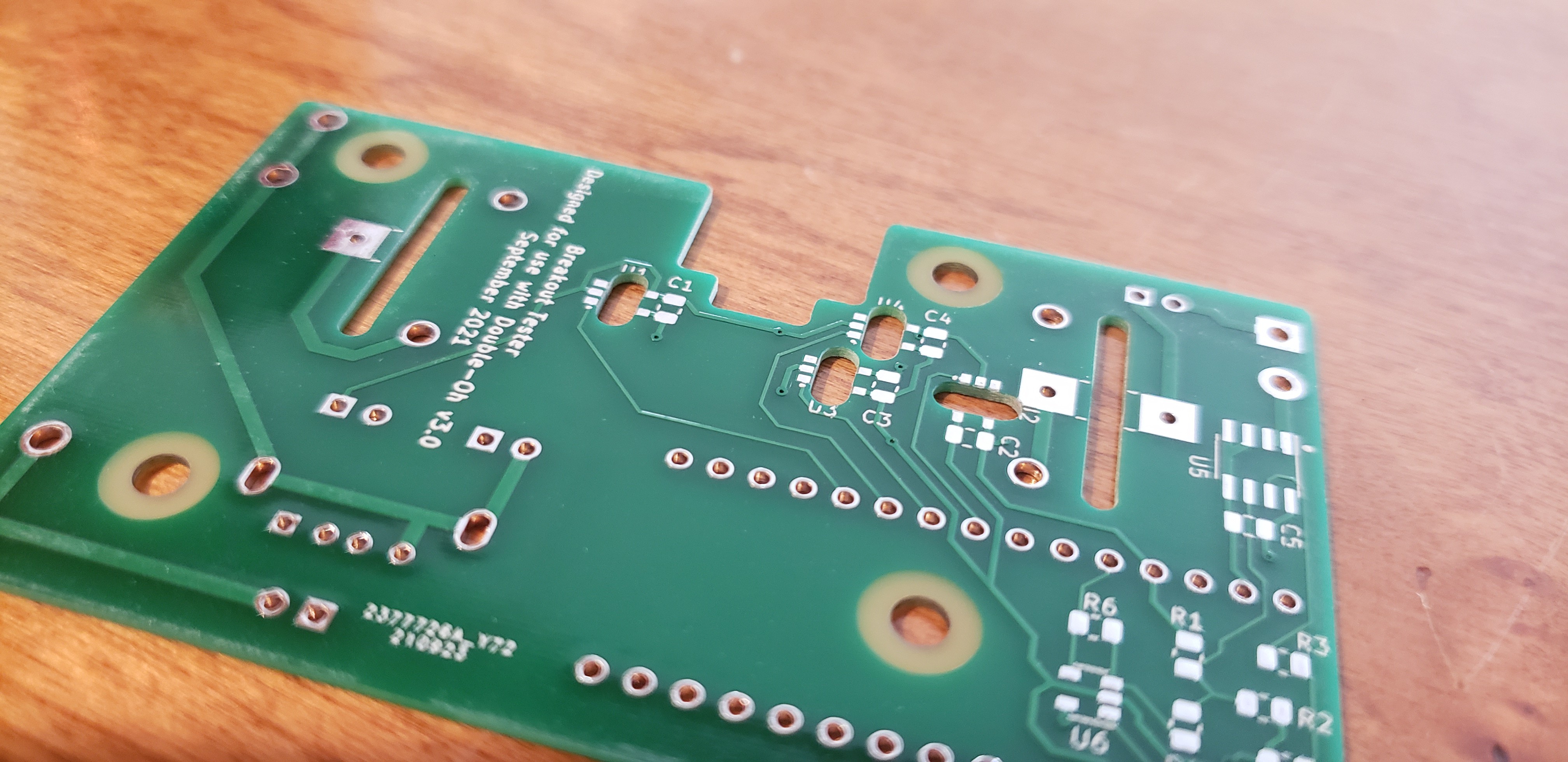
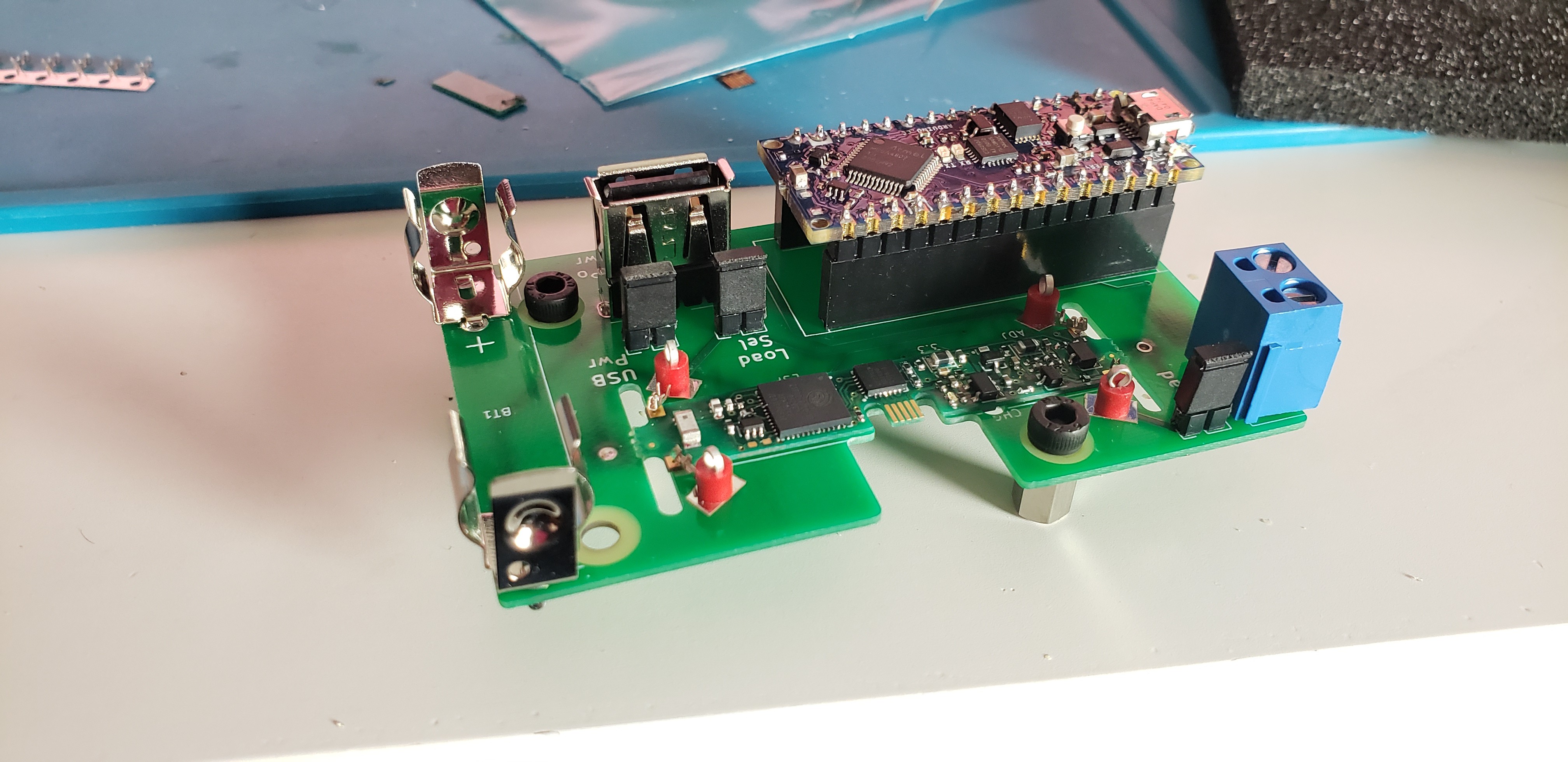
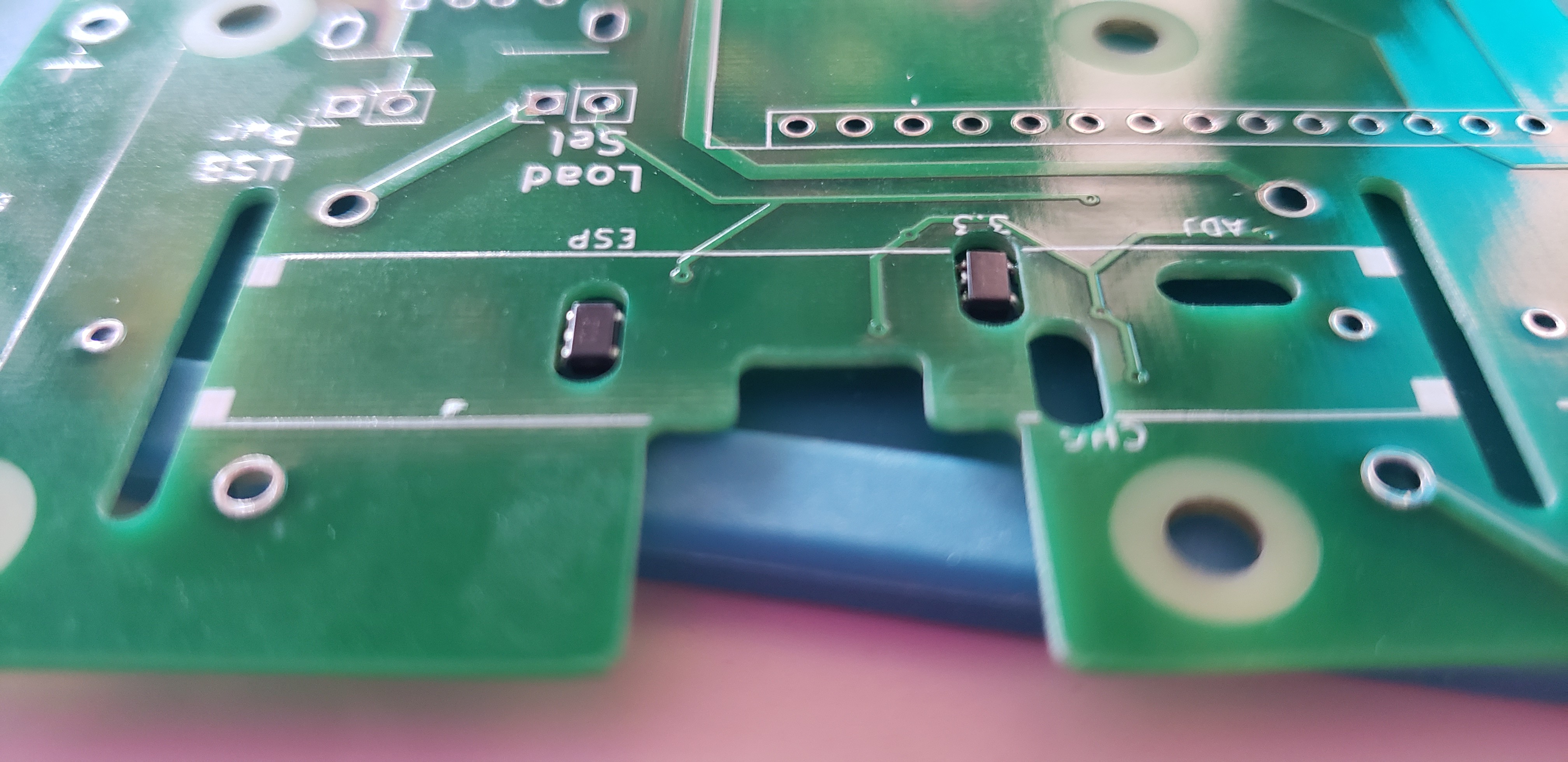
This jig should let me try different loads, measure the IC temperatures, and monitor the current drawn by the load and the device as a whole. And, perhaps most importantly, I can keep a USB cable attached for debugging and serial logging. There are a couple nifty parts of the test jig that I'd like to emphasize. First, the TMP35GRT temperature sensors: there are four in total, pressed up against the underside of the PCB in the test jig. To lie flush with the PCB, they're placed upside-down in slots, like so:
Now how is the Double-Oh held in place? The system I went with works, but I don't like it very much. I could use some alternate suggestions!
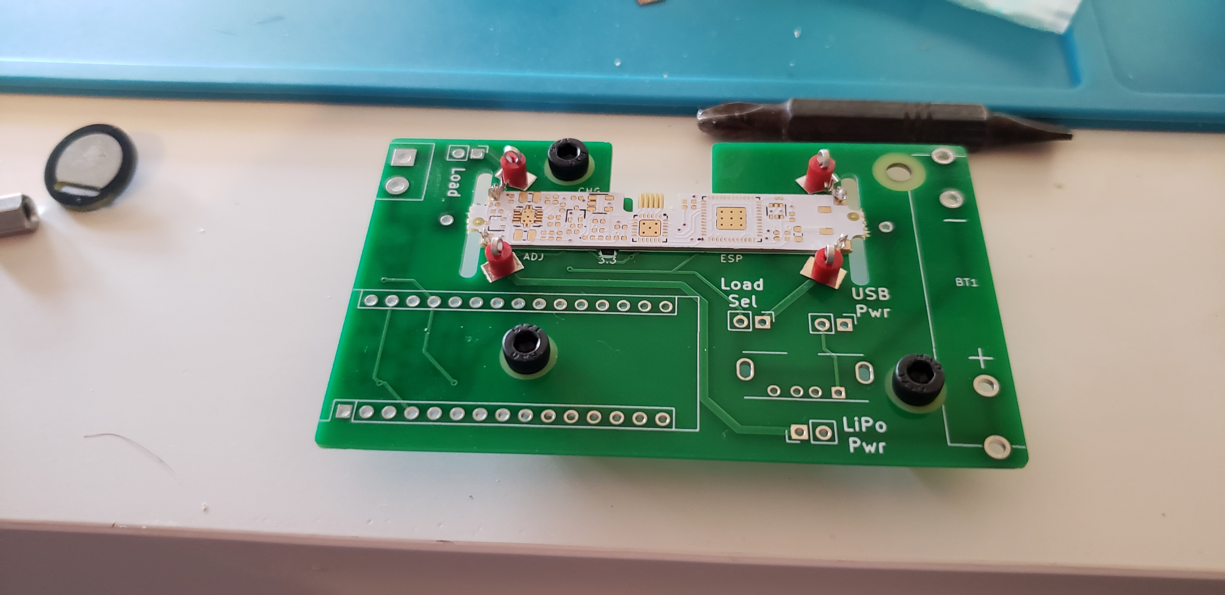
Those arms holding the Double-Oh in place? They're Molex connector contacts with the bandolier strip still attached! They are intended for the PicoBlade, not...whatever this is. A removable test point secures it tightly enough to stop the Double-Oh from moving, while also letting me swing the contacts out of the way when necessary.
For measuring the load: the chip shortage compelled me to use the TMCS1100A4 current sensor, which has analog output and a sensitivity of 400 mV/A. Since I only plan to test loads between 0 and 1 Amp, that means the TMCS1100A4 output will in the 2.5-2.9V range—not great for an Arduino and analogRead(). An op-amp stage should, hopefully, convert that to a 0-3.3V range that I can measure more easily. The sensors are being monitored by an Arduino Nano Every—well, they will be, once I write the Arduino sketch....
Discussions
Become a Hackaday.io Member
Create an account to leave a comment. Already have an account? Log In.