 John Anderson
This project has been completed. If you are interested to read about additional features I am adding with subsequent builds of this concept, like and follow the latest project: 1979 "Heathkit" D&D Digital Dice Tower
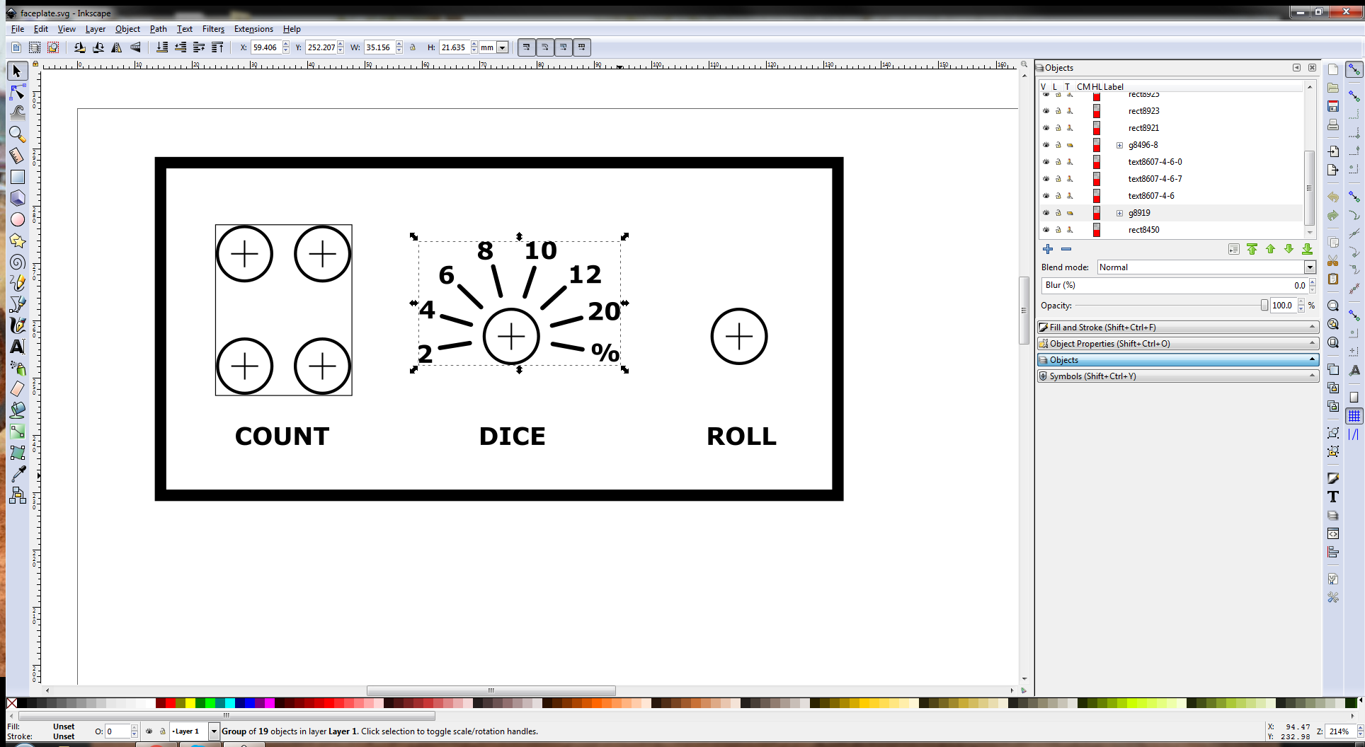
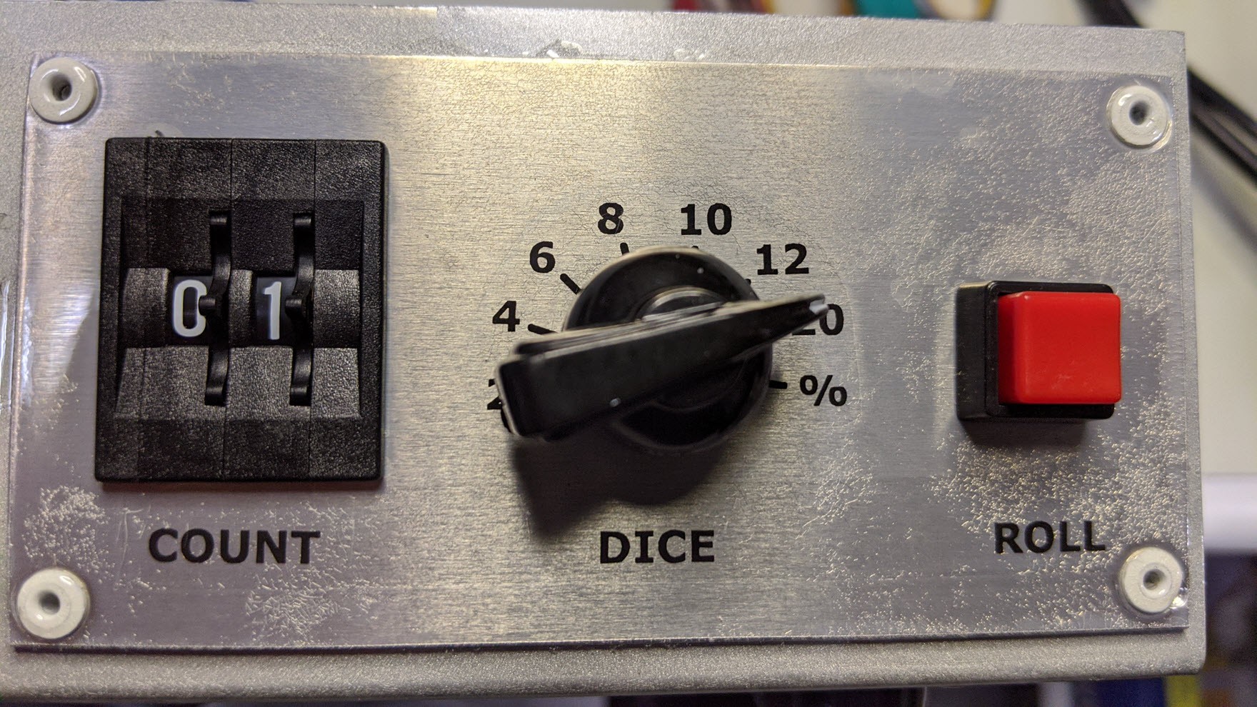
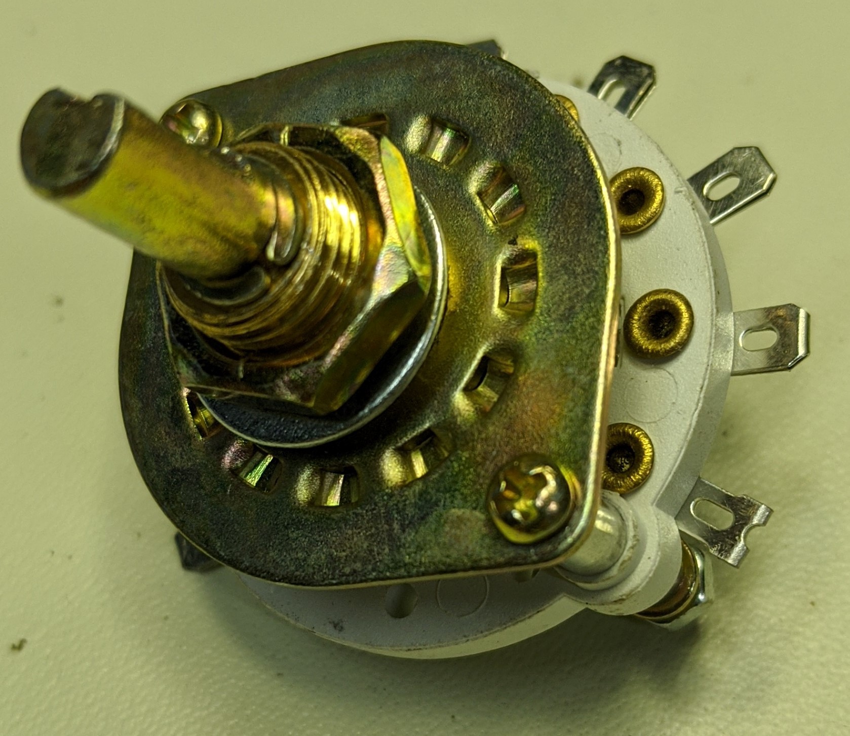
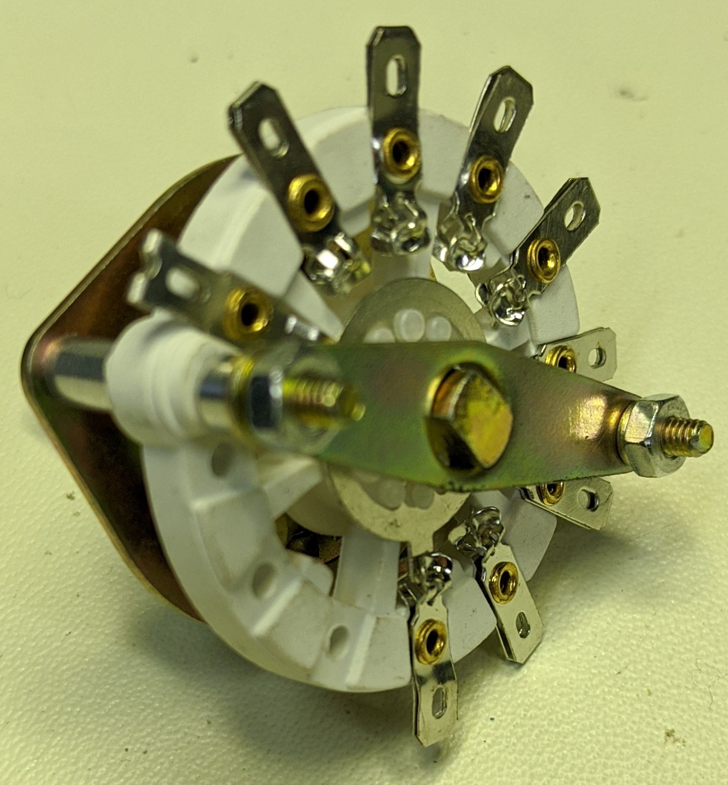
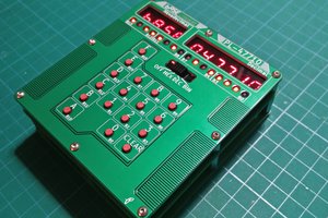
This project implements the function of a Dungeons and Dragons dice tower and dice using a retro digital multimeter with nixie tube display. The user selects a number of dice using the two digit thumb-wheel switches, then selects the dice type (2 sided, 4 sided, 6 sided, 8 sided, 10 sided, 12 sided, 20 sided, or 100 sided) using a rotary switch, and finally presses the roll button to get a result. The device applies the GNU AVR lib C pseudo random rand() function, calculates the result, and displays it on the nixie tube display. The user can then re-roll by pressing the roll button again, or change the count and/or dice and roll a different set of die. It's that simple to use.
This project represents several things l love.
- It's Dungeon & Dragons: I've been playing D&D since 1978. Thus 1978 is in the project name and it's a resto-mod build based on user interface technology from that same time frame.
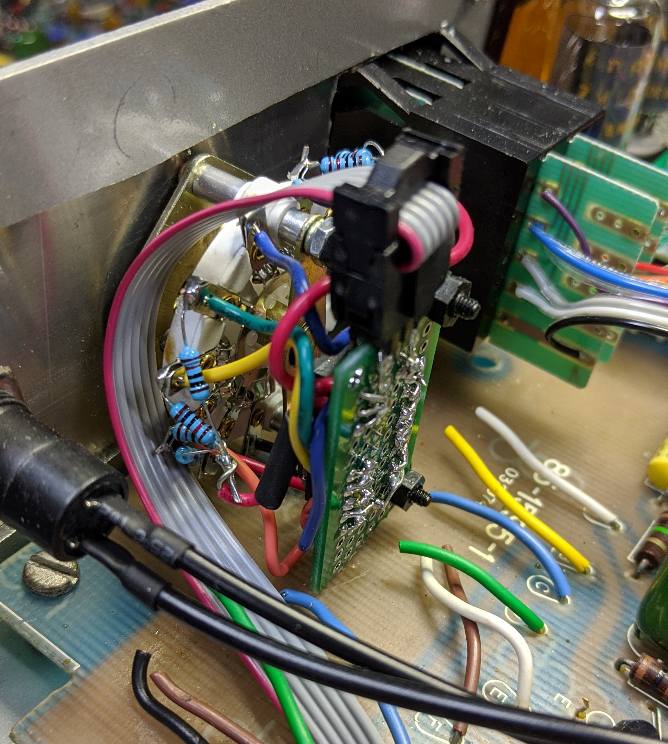
- It recycles: It's fun reusing old parts and technology. Besides being "the right thing to do" for reasons we already know, "Recycling" requires disassembly and reverse engineering. It's fun to take things apart and figure how they work. I often learn things applicable to other projects in the process. "Recycling" also requires a different approach to design and implementation. It defines the space you are working in and presents challenges that force you to look at projects from a different perspective. If you do it right, you can even avoid the boring parts of a project like designing a 170V power supply from scratch. I have a CS degree, not a EE :-)
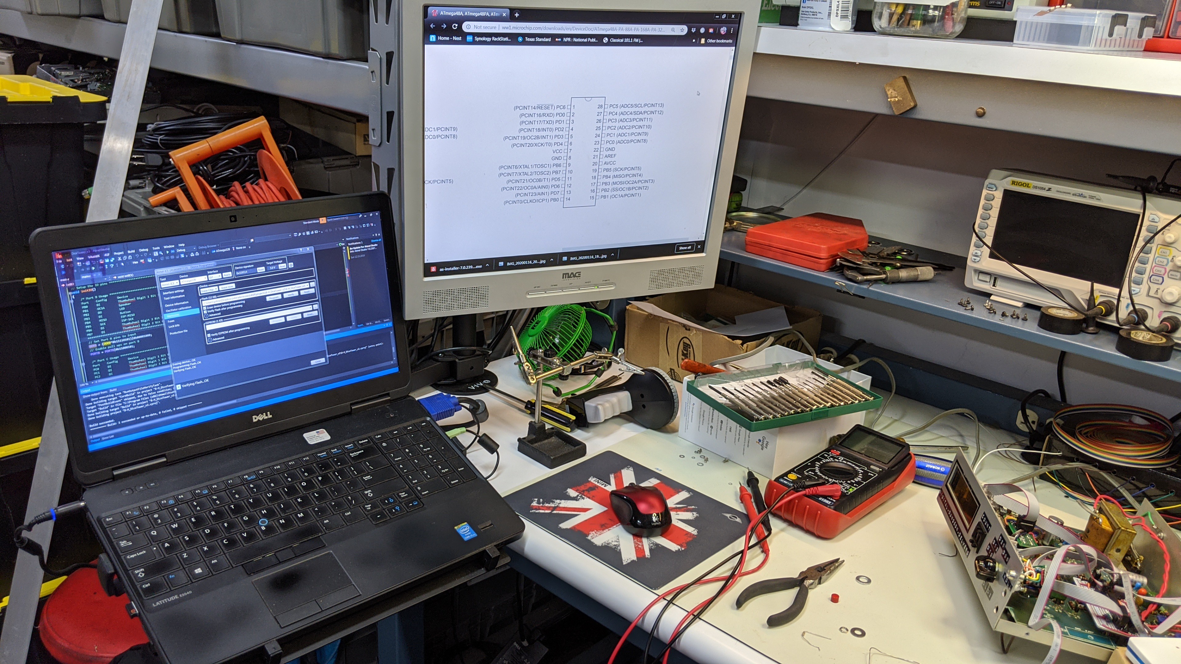
- There's a microcontroller: A project just isn't fun unless there's a microcontroller and some software to write, download, debug, and iterate. I have a CS degree, not a EE :-)
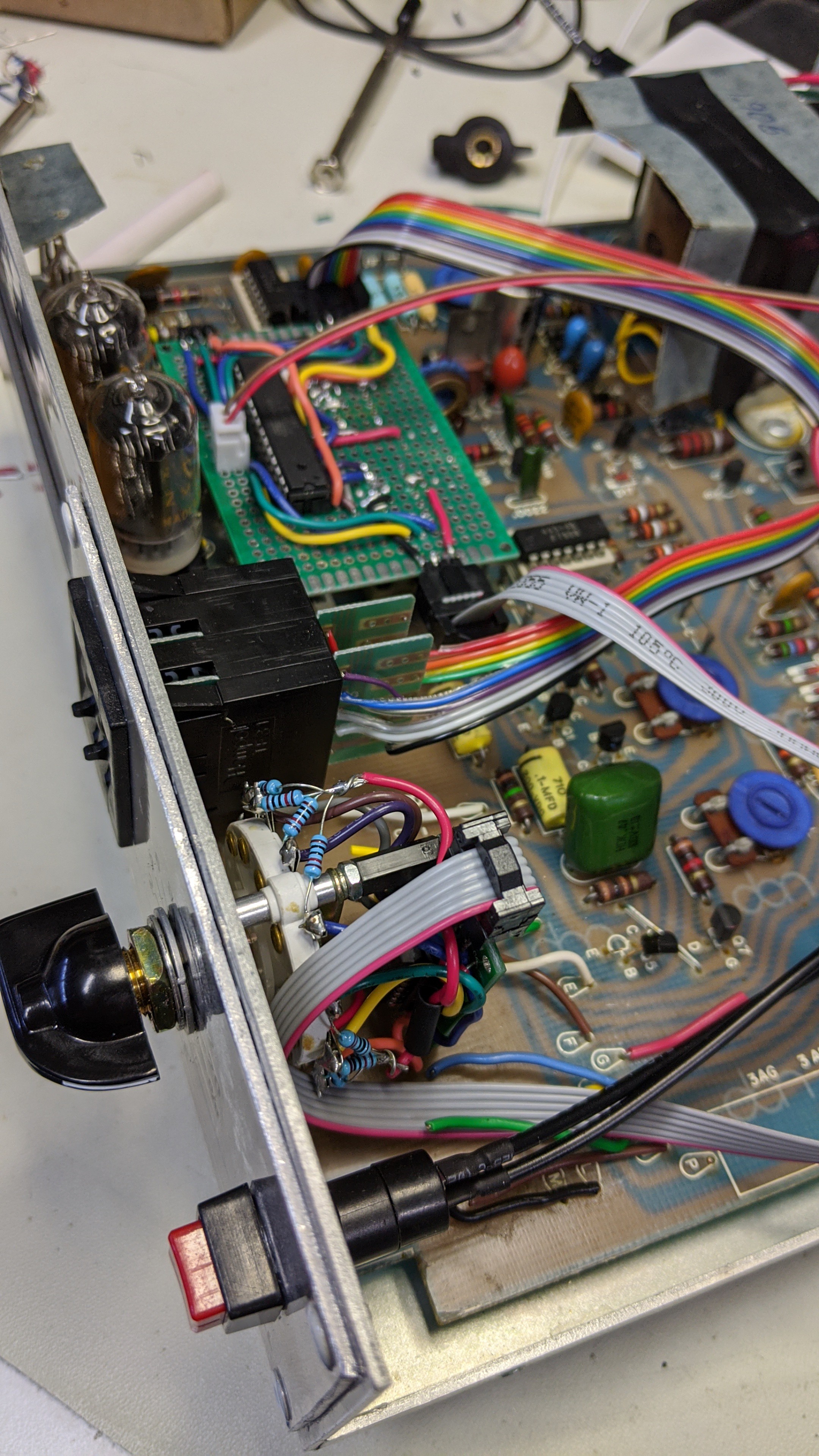
- It's retro-cool without the retro software development: I love the old display technologies, the classic panel mount switches/dials/buttons, wrinkle paint, "lab equipment" blue, and sheet metal cases. I appreciate the 74xx series logic IC's and big through hole parts on the PCBs. They simplify reverse engineering, hardware prototyping, and the tools/skills required to do it. I even dig the old 8 bit processors (z80, 8051, 8088, 6502, 6805, 68hc11, 68K). In the past, I've written C and assembly code for all of those processors. However, I'm not a big fan of antiquated software development environments and code libraries, or spending hours integrating old tool chains with modern IDE's. I prefer to stay current with my software development and keep it applicable to the current job market. Thus the resto-mod approach using the AVR microcontroller.
- It's nixie tubes in an application that doesn't tell you the time of day: I saw someone post a comment the other day that nixie tubes are "boring now". I disagree. Nixie tubes are still cool. We just need to find new applications other than displaying the time of day.
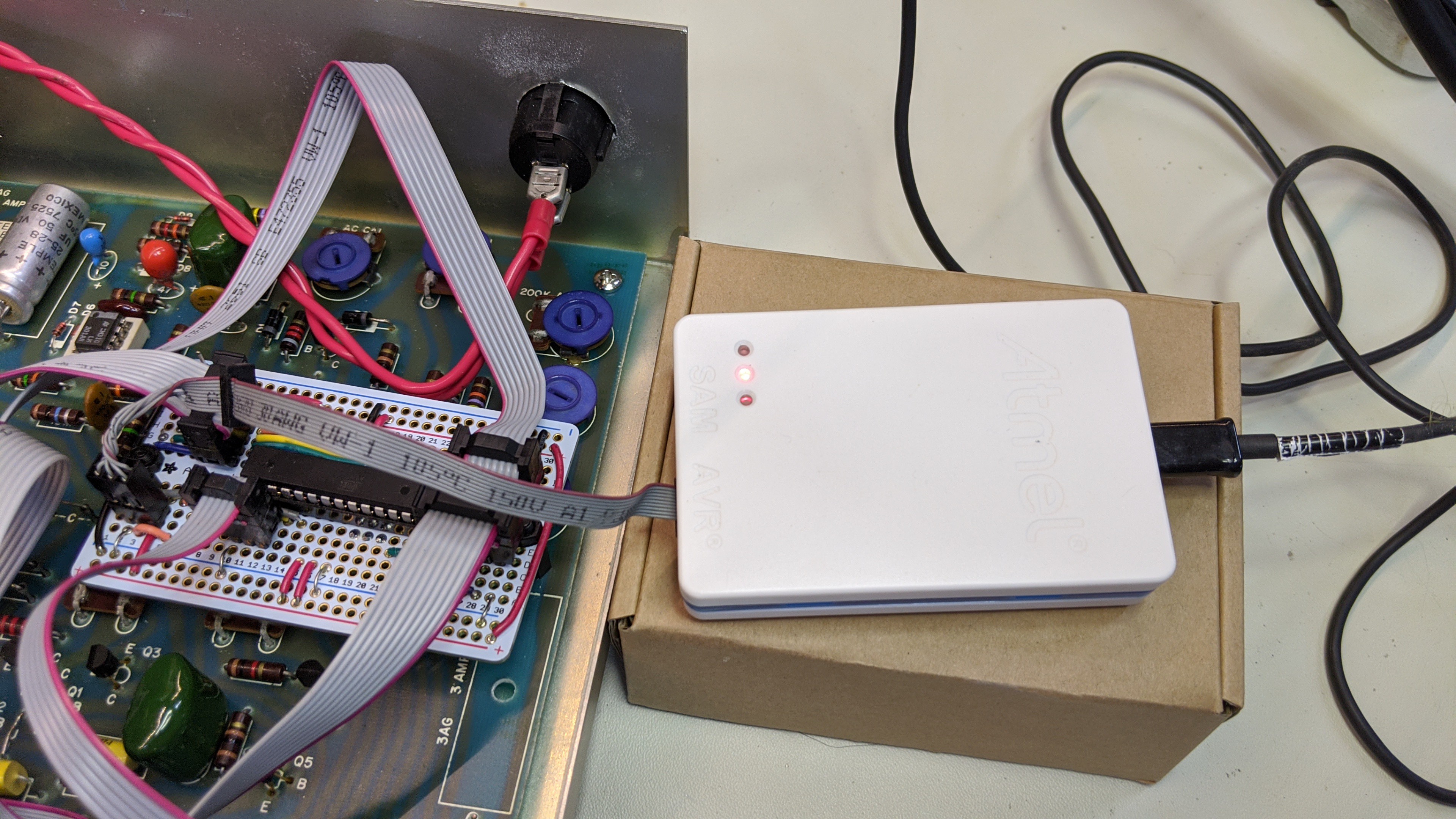
I'll add some project logs with more detail on how this project was built. For now, here's an overview of the pieces required to make this work and how they roughly fit together.
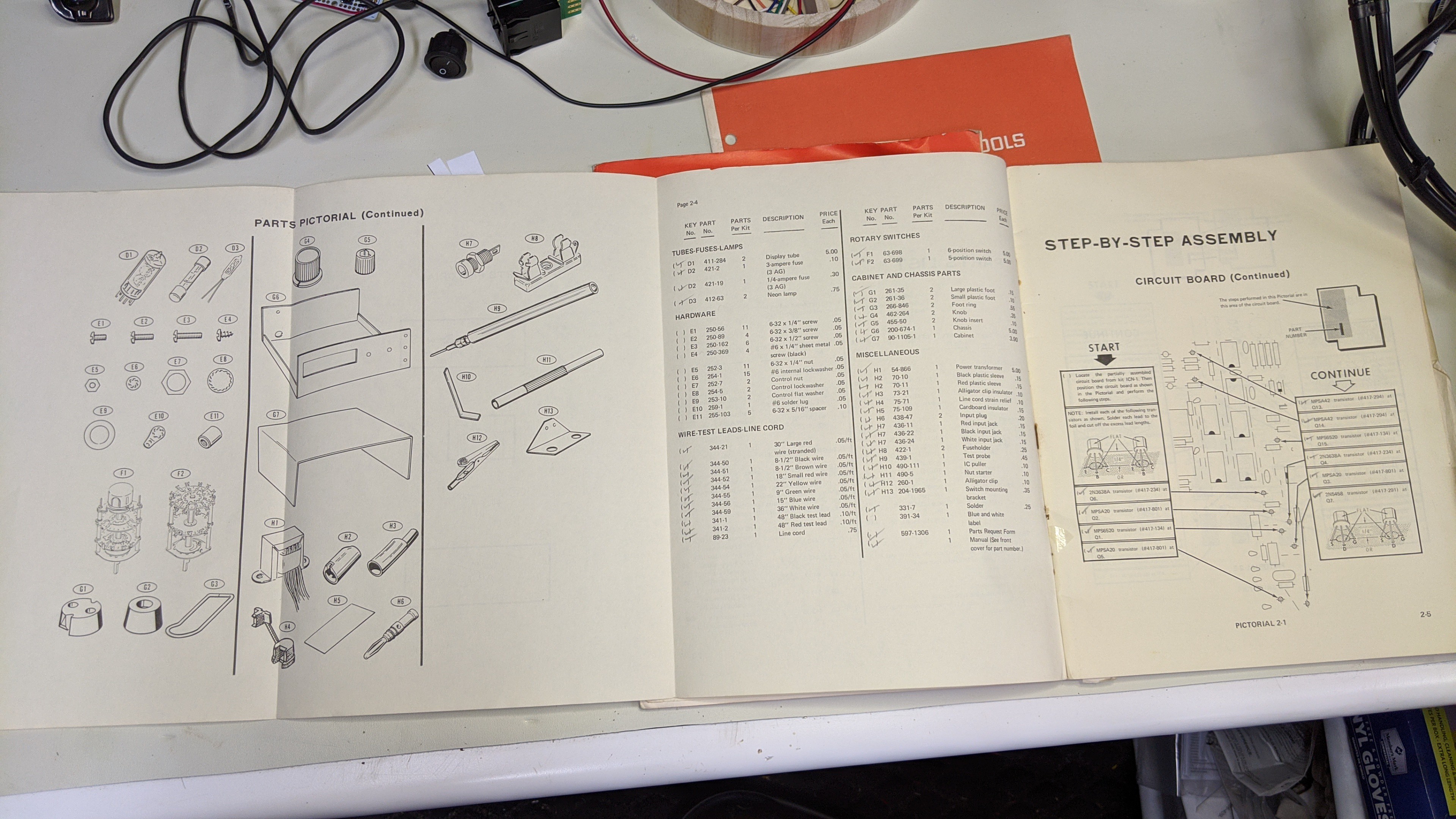
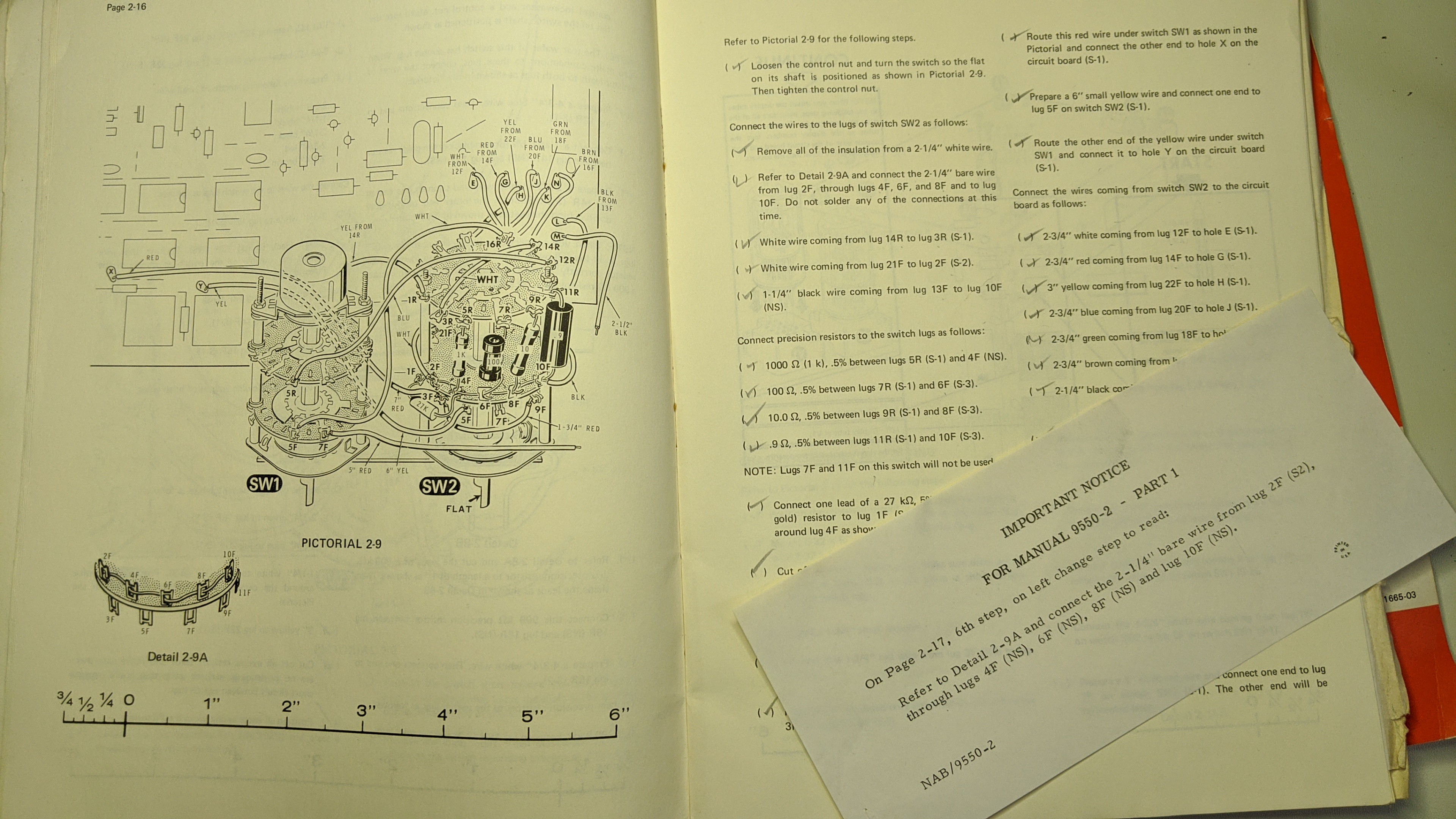
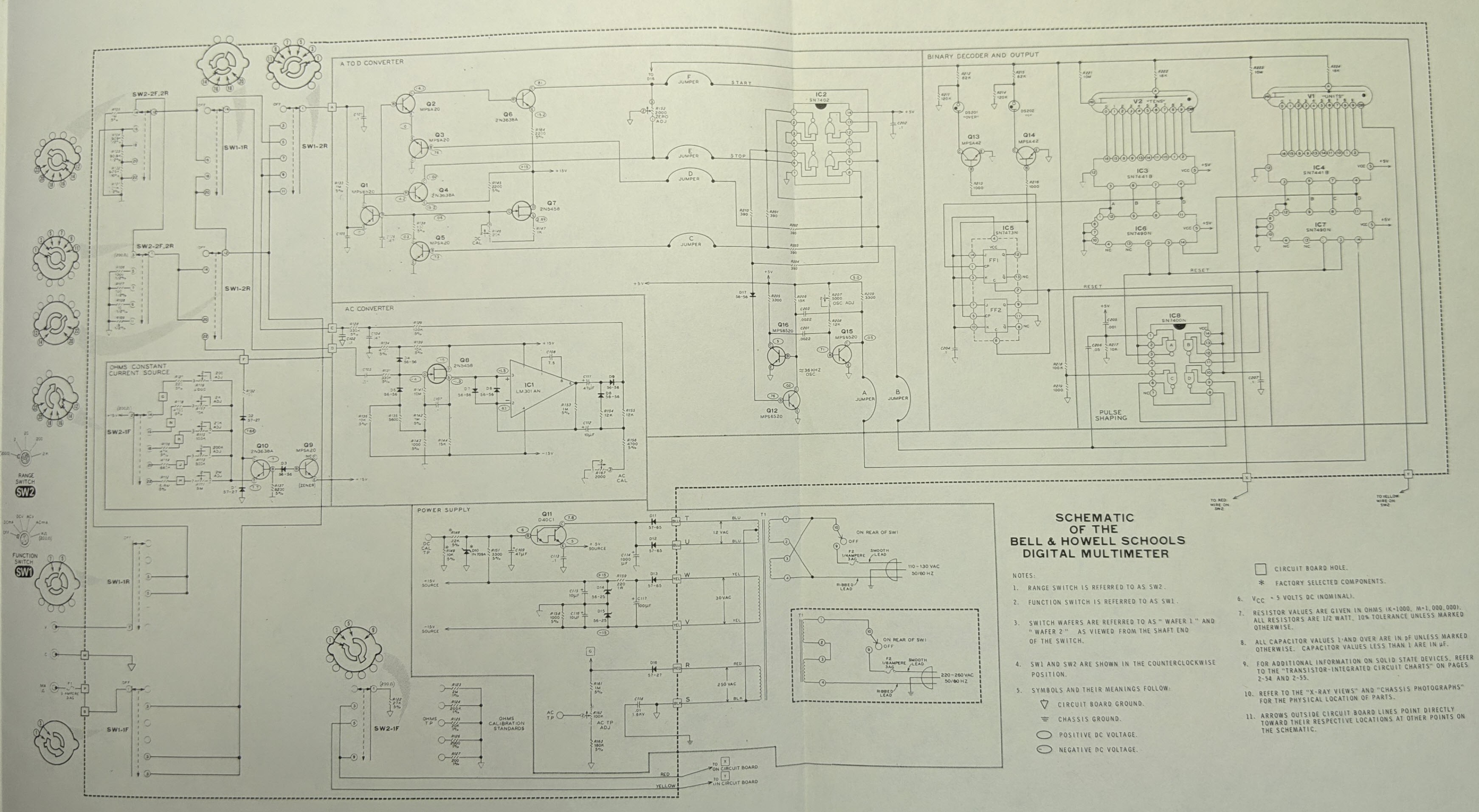
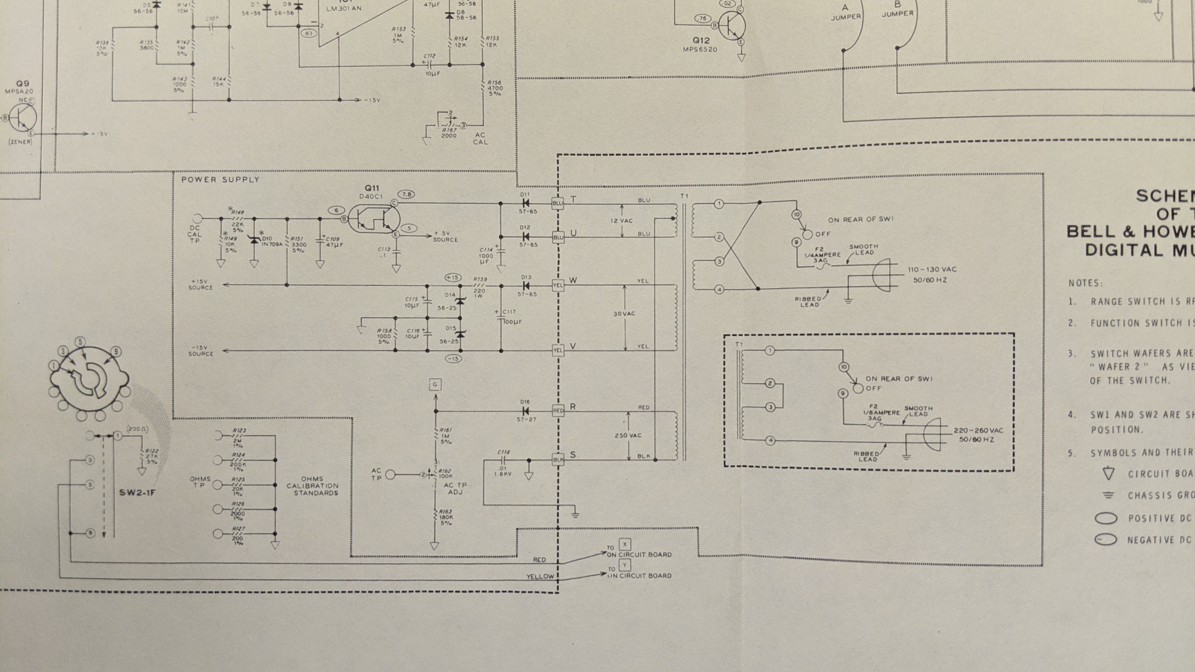
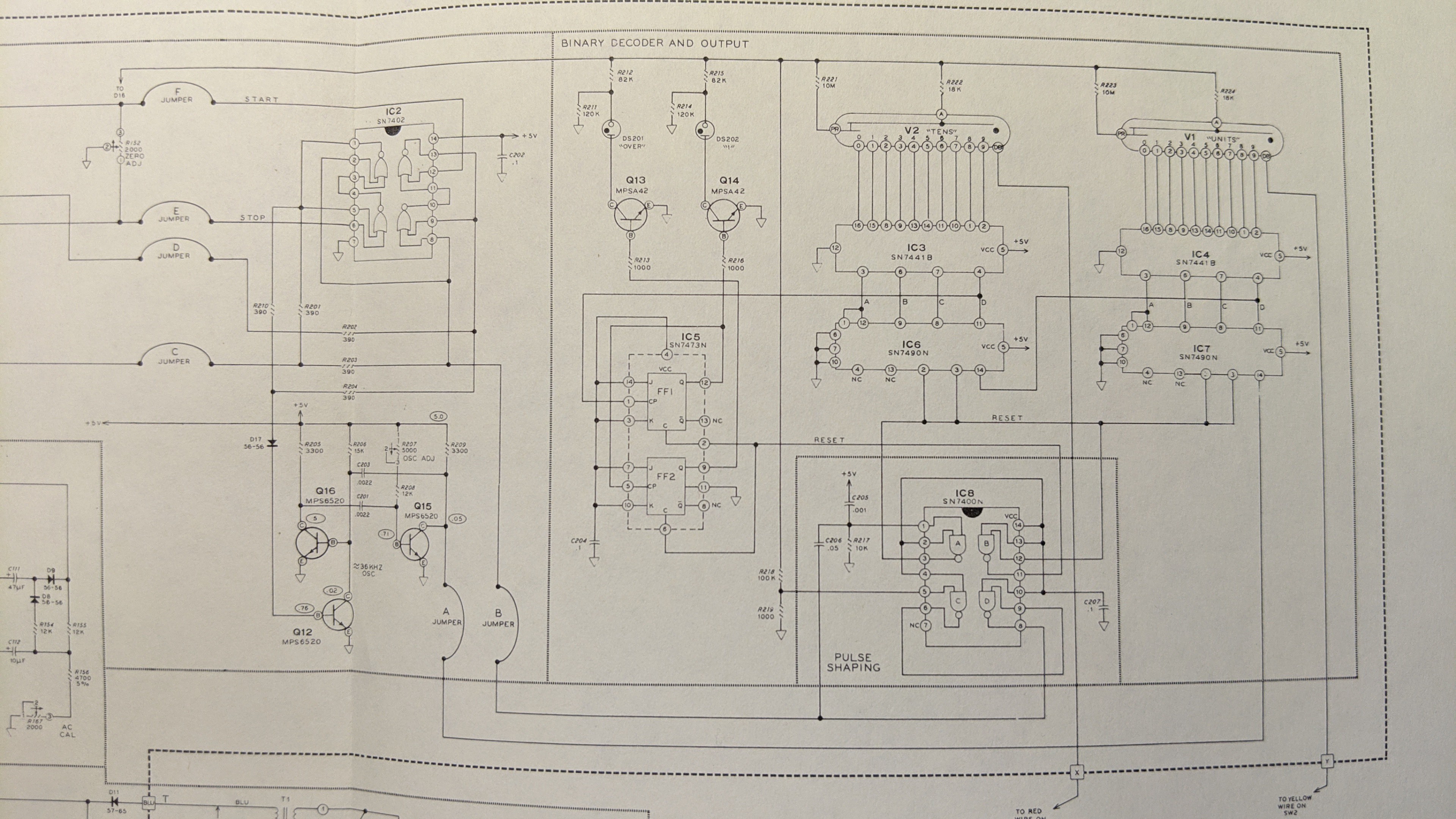
This project "recycles" a Bell & Howell IMD-202-2 Multi-meter. These devices were part of the DeVry University electronics curriculum back in the mid-70's. If I understand it correctly, this multi-meter was a project that students built. The design is based on a Heathkit IM-1212 multi-meter. Bell & Howell apparently acquired the rights to recreate that design in a different form factor and enclosure. These multi-meters were produced in fairly large numbers. You might have one in your attic right now. Or, you can easily find functional examples on eBay. If you have a little patience, you can even buy them cheap. By cheap, I mean cheap for a project case, a couple nixie tubes, a couple...
Read more »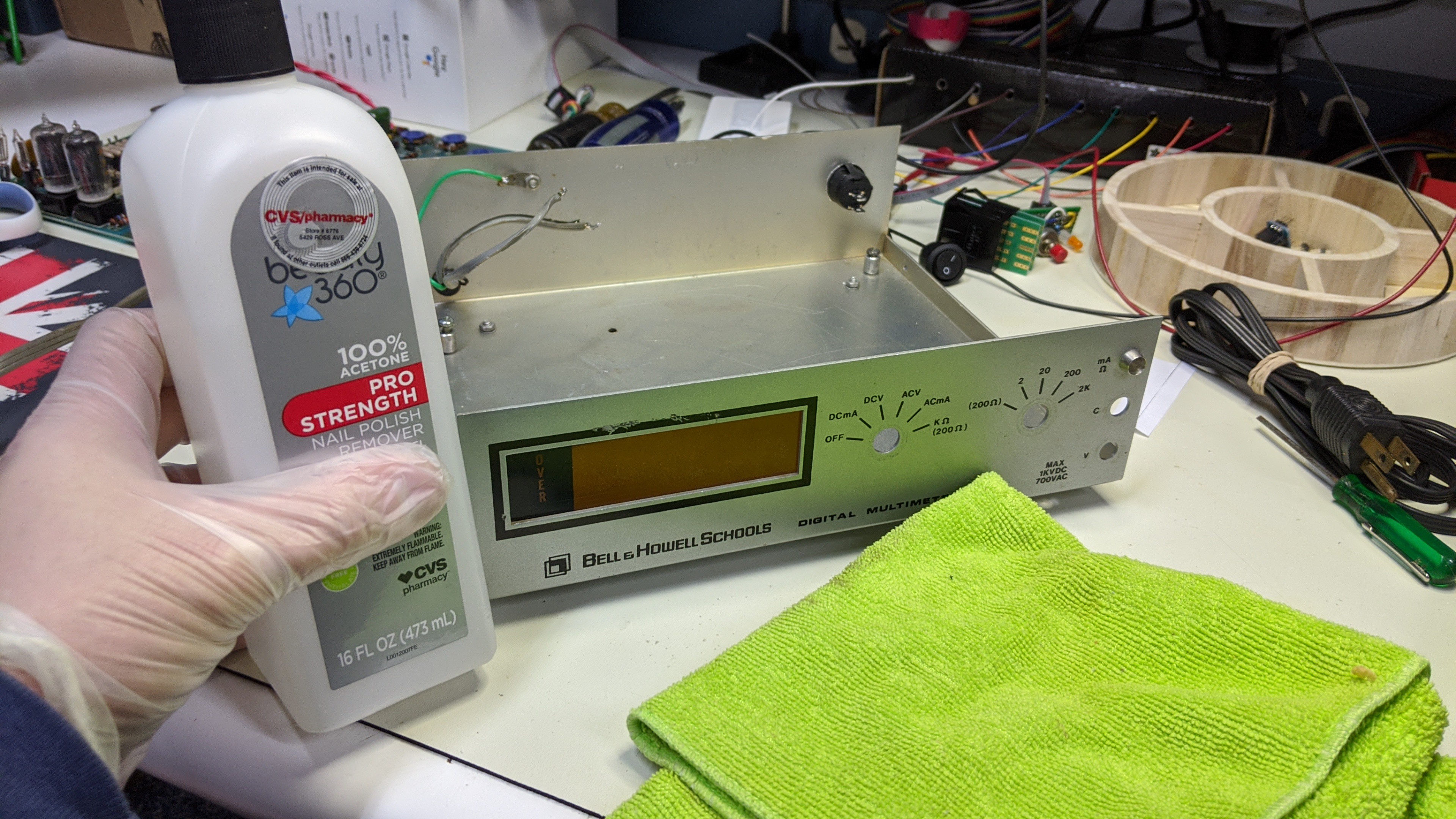


 leumasyerrp
 Alan Green
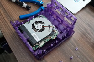
 Jamie Searle
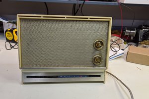
👍 I like your recyling elevator pitch. More ideas to digest.