 John Anderson
As mentioned in the details of the project, this mutlimeter was originally a kit that DeVry students assembled during their course work. So, there is some design documentation and even a schematic available for it if you do a little searching on the inter-webs. I couldn't find any original Bell & Howell or DeVry documentation of this actual device. But, I quickly discovered it's based on a Heathkit IM-1212 digital multimeter with nixie tube display. A brief search turned up a pdf version of the original Heathkit assembly manual. The same search also turned up some confusion around who owns the Heathkit intellectual property and their intentions. So, I won't post the full assembly manual here. But, I will provide a couple relevant excerpts. If you want more detail, you can easily find the same IM-1212 Assembly Manual. There's also a good overview and description of the circuit design for this meter on Mr ModemHead's blog. You can find it here: http://mrmodemhead.com/blog/nixie-glow/
For dice tower application, I wanted to reuse the case, 7441 decoder/drivers, and nixie tube display. But, after a little research and reverse engineering, I realized it could also reuse the power supply as well. Doing so would require hacking up the single large PCB, or just leaving it in place and adding my simple protoboard with AVR. There's plenty of room, so I left the PCB as it was.
Now I just needed to figure out how to connect the new stuff to the old stuff. Glancing at the schematics, BOM, and part details it quickly became obvious that this could be simple.
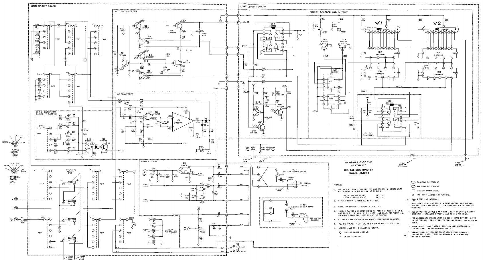
That's the whole schematic. It's not very useful at full view, the scan quality is low. But if you zoom into the upper right quadrant, you can see the detail needed.

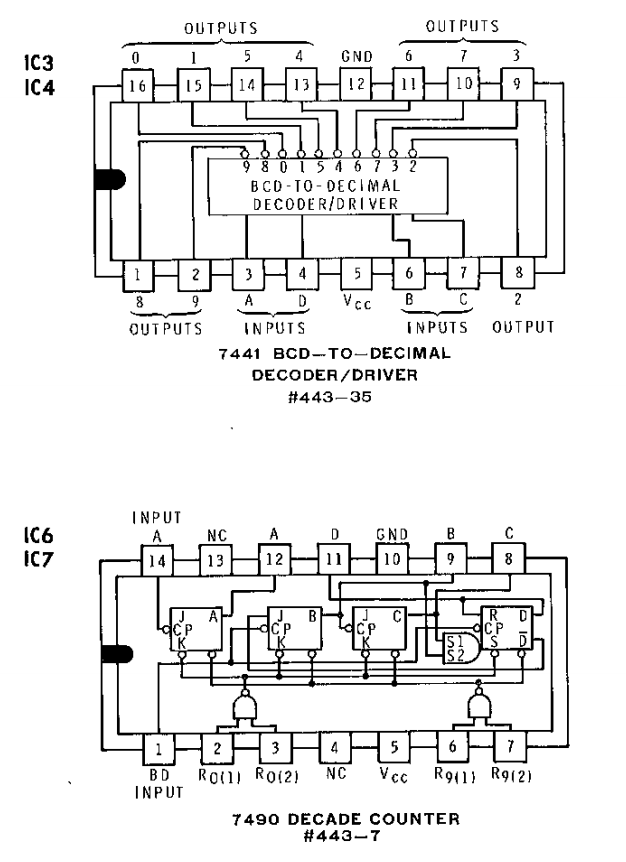
IC6 and IC7 are 7490 decade counters. They count the clock cycles generated by the single-slope voltage-to-time ADC (see the Theory of Operation as it's described in the link above). Since I'm ditching all the analog multimeter functionality, I don't need those. Conveniently, they are directly connected to the 7441 decoder/drivers that I do want to interface. In addition, the 7490's require Vcc (5V) and GND, and they are socketed on the board. So, those sockets have everything I need to interface my controller board with the nixie displays and power supply.
I located the parts on the board (labeled 1 and 2).

Popped them out of the sockets, trimmed a couple socket (female) headers to length, and installed in the sockets to give clearance for the controller board. Note: I also removed the old rotary switches in this picture. I'll document that in another upcoming log.

I decided to test this approach before warming up the soldering iron. I pulled out my breadboard, jumpers, and ATtiny88 and wired up Vcc, GND, and 4 pins of one of the ports, configured them as outputs, and wrote some values to it. It worked.

Now confident the approach would work, I trimmed a couple single row headers to fit, placed my empty proto-board on the headers, and positioned it as I wanted it. I soldered the headers right there in place so they lined up with sockets perfectly.
The next step was to pull the proto-board out of the sockets, put it on the workbench, solder down a 28 pin DIP socket for the ATtiny88, wire up/solder Vcc and GND, and then solder the connectors, wire them up, and solder some more.
It looks like this when completed.


It's ugly. But, it works :-)
I glossed over some detail there and I'm not going to provide a schematic for the controller board. It's just some wires connecting the processor pins to Vcc, GND, an ISP port, and 5 connectors. I soldered it up looking at a pinout diagram for the ATtiny88. If you need some help wiring up a 6 pin ISP port for the AVR, checkout this Atmel document for more information: AVR ISP User Guide
I'll document which ports connect to which IO functions in the log covering the project software later this week.
Discussions
Become a Hackaday.io Member
Create an account to leave a comment. Already have an account? Log In.