 John Anderson
Now that I had the control board proven and integrated with the nixie displays and power supply, I needed to figure out how to install the input switches and button required. To do so, I first needed to remove the old rotary switches and banana style connectors.
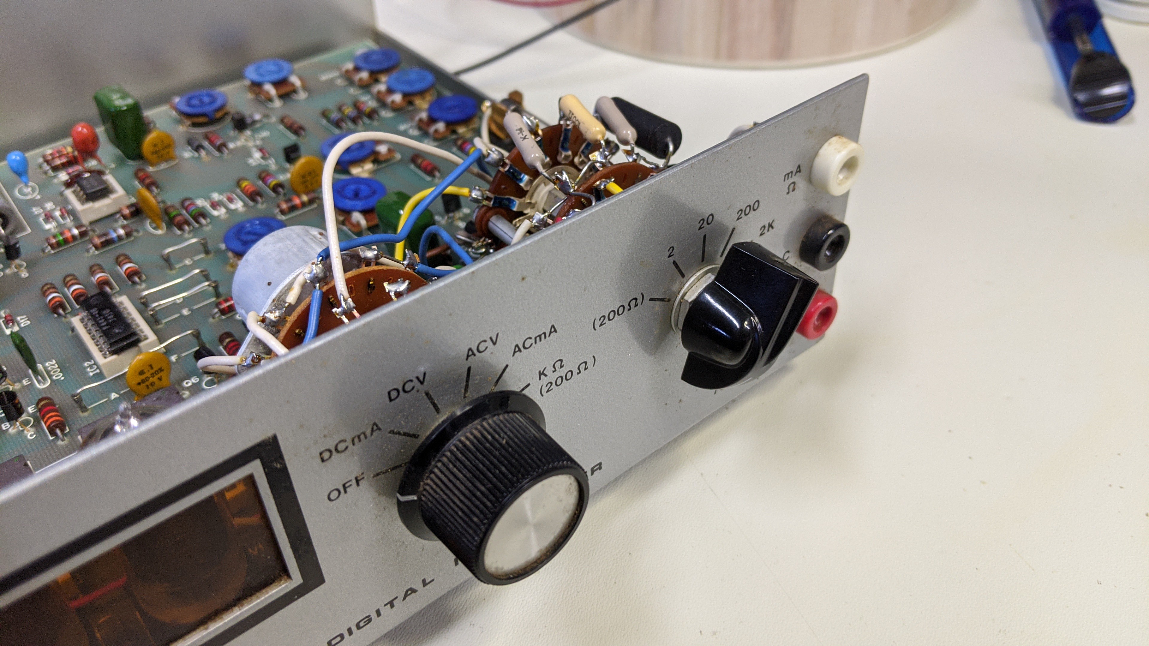
The wires connecting these to the PCB are soldered to the board. I cut them at the board so I didn't have loose wires shorting to things they shouldn't. The exception was the two wires that switch the 110V AC on/off. These two wires originate at the power transformer and fuse at the rear of the PCB. They pass under the PCB and pop out under the left rotary switch and connect to the back of it. I clipped the wires there to leave plenty of slack so I could run them to a new on/off switch. The red arrow in the picture below points to these two wires where they connect to the rotary switch. The blue arrow points to a fuse you can remove along with the banana style connectors.

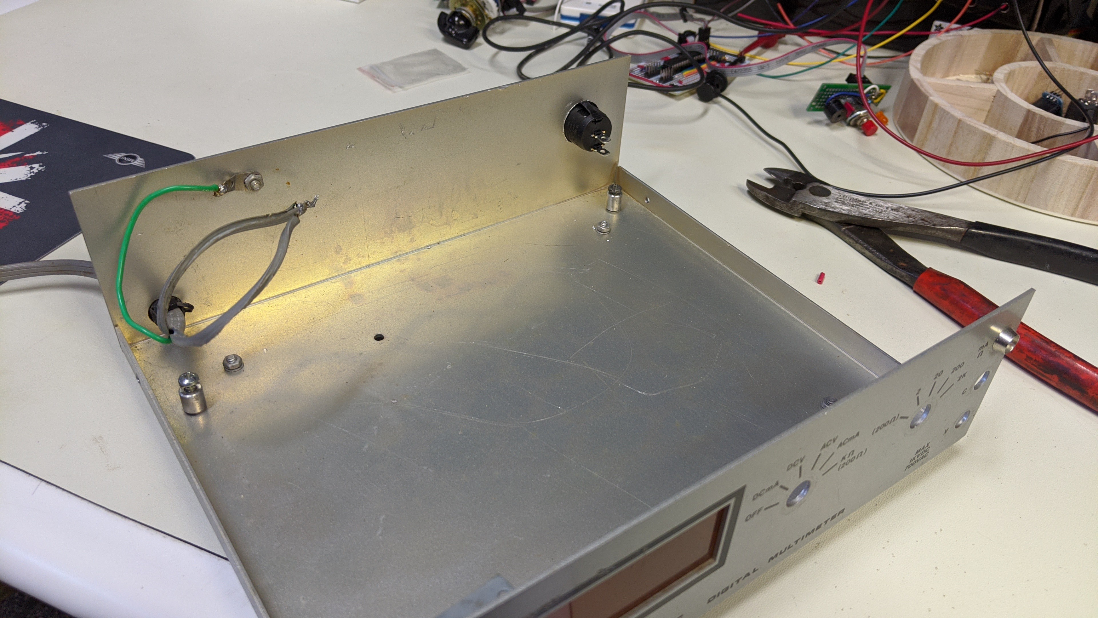
Once the the switches and connectors were removed from the faceplate and the cut from the PCB, I removed the PCB from the case. At this point, it looked like this.

Next, I drilled out a 3/4" hole in the rear faceplate of the case to mount the power rocker switch. Using a step bit made this easy. Then I used a small square file to notch one side of the hole for the key that prevents the rocker switch from rotating in the hole.

It looked like this when I pressed the switch into the new hole.

Next I crimped a couple blade connectors to the AC on/off wires I trimmed for the rotary switch earlier.

At this point, I was ready to start laying out the new switch interface and figure out how to make it work with the existing faceplate.
Discussions
Become a Hackaday.io Member
Create an account to leave a comment. Already have an account? Log In.