 Miroslav Zuzelka
I was prototyping a lot and here is wrap up what I went through.
1) Research and CAD
I´m making this design parametric (where it make sense) so you do not have to change value on 10 different places through design file.
As I mentioned I´m inspired by Openplacer so I decide that I will use same diameter for linear rods and similar bearings for rods so I can use dimension in blueprints for start. You can find HW dimensions on their Downloads and manuals page. I put these in CAD (Fusion 360) and I changed them to be 3D printable a and added mounting holes and gaps for nuts (front and back pieces for Y axis) and I added belt holder for central piece on X axis. I decide to use same GT2 belt as Prusa company is using on their printers as it is largely available and it should not be problem to buy it anywhere. I bought linear rods here in Czechia as I do not want to wait till will arrive and also my friend told me that rods form China will be more like butter and if I want real steel, I should buy it locally so I recommend that to anyone.
Because you can not buy a lots of things locally, or at least not in hacker friendly price, you have to look what China offers. I will post links to things which I ordered so if anyone decide to build this, can use same parts, but for sure you can use your own or choose different one.
Here is list of items which you will need to order from overseas:
- cable chaine 18x25 mm + cable chaine 10x15 mm
- 12V vacuum pump
- Juki nozzle
- top camera
- light circle for bottom camera (40 mm diameter)
- 12V solenoid valve (normaly open) or 12V solenoid valve (normaly closed)
- stepper motor for Z axis (depth 23 mm)
- GT2 pulley with 5 mm bore
- Nema 8 motor with hollow shaft (if you want to use stepper motor for nozzle instead of servo)
I will also try to make some Google spreadsheet with all components which need to be bought and I will post link in parts section of this project.
2) First test
Because I ordered rods, bearings, pulleys and belt locally I could make first steps with this design quite quickly. After that what I designed belt holders for Y axis, I printed all parts and make first assembly. This was done in day or two as it is very simple to build it.
I used my board based on ESP32 in Arduino Mega shaped PCB which is using RAMPS board for driving stepper motors. I will use this as development platform and after that I will design separate board to drive all components of the PnP machine. This will be covered is separate project.
3) Head assembly design
This is part which took me the most of the time in last month or so..
Because this has to be printable as well, I looked around the Internet and I found one project on Github for Juki nozzle holder. Because I was planning put this holder in to the 608 bearing, I modified it in Fusion 360 and tried to print it on Prusa i3 Mk3 printer. Result was not so bad, but even when I was able to stick it in to the bearing, the part was to fragile and quickly broke. I was thinking how can I make it stronger and I realized that my friend Jan Mrázek was offering me print on SLA printer. I asked him and he was very kind that he printed this piece for me. Result was much more stronger and very nice looking piece. It has smaller diameter, but for testing it was ok.
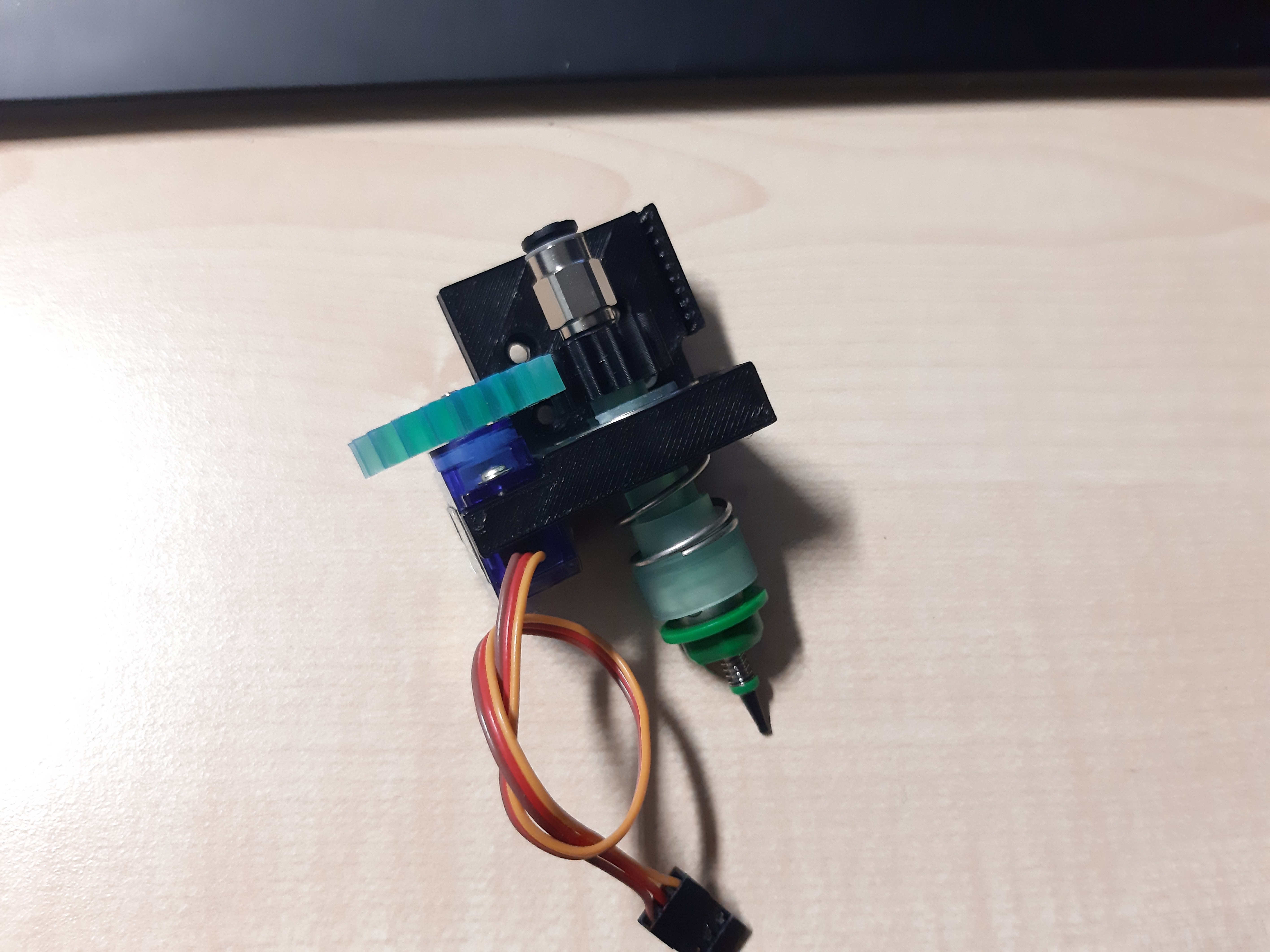
I designed holder for bearing and servo so it can be mounted to the head holder.
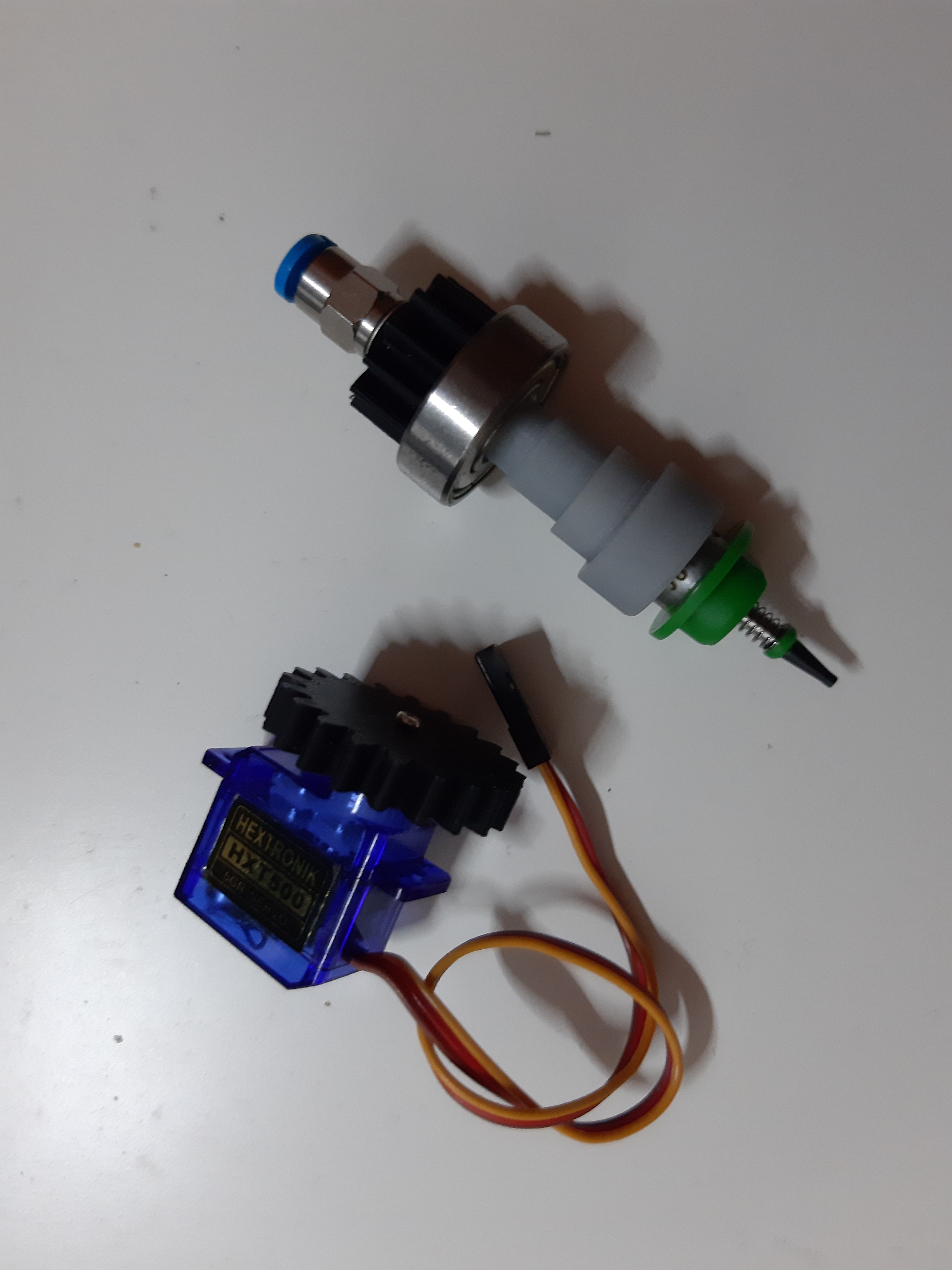
As I want this to be as affordable as possible, I wanted to design head with servo motor, which will spin nozzle in some direction to align it with spot where component should be placed. At first I planed to use normal servo, which you can rotate in 0 to 179°, but I was not sure if I will make it to work with control SW as this can rotate component in positive or negative direction. This task surely can not be achieved by servo which goes just in positive direction. I knew that you can modified one to just spin in one or other way, but did not know that you can buy one which is already continuous. Luckily I found that before I start to dismantle some, so I bought 5g and 9g servos for testing.
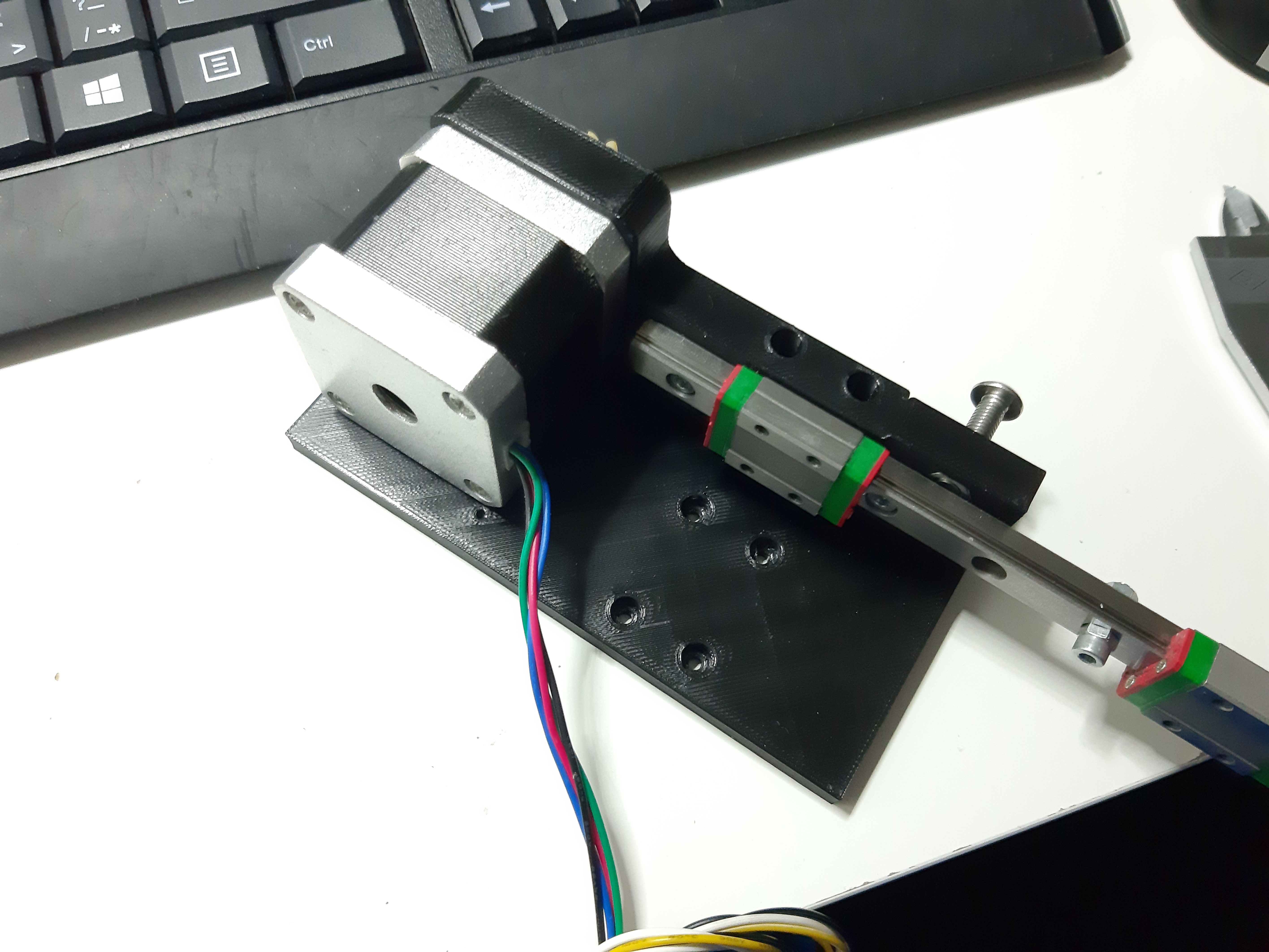
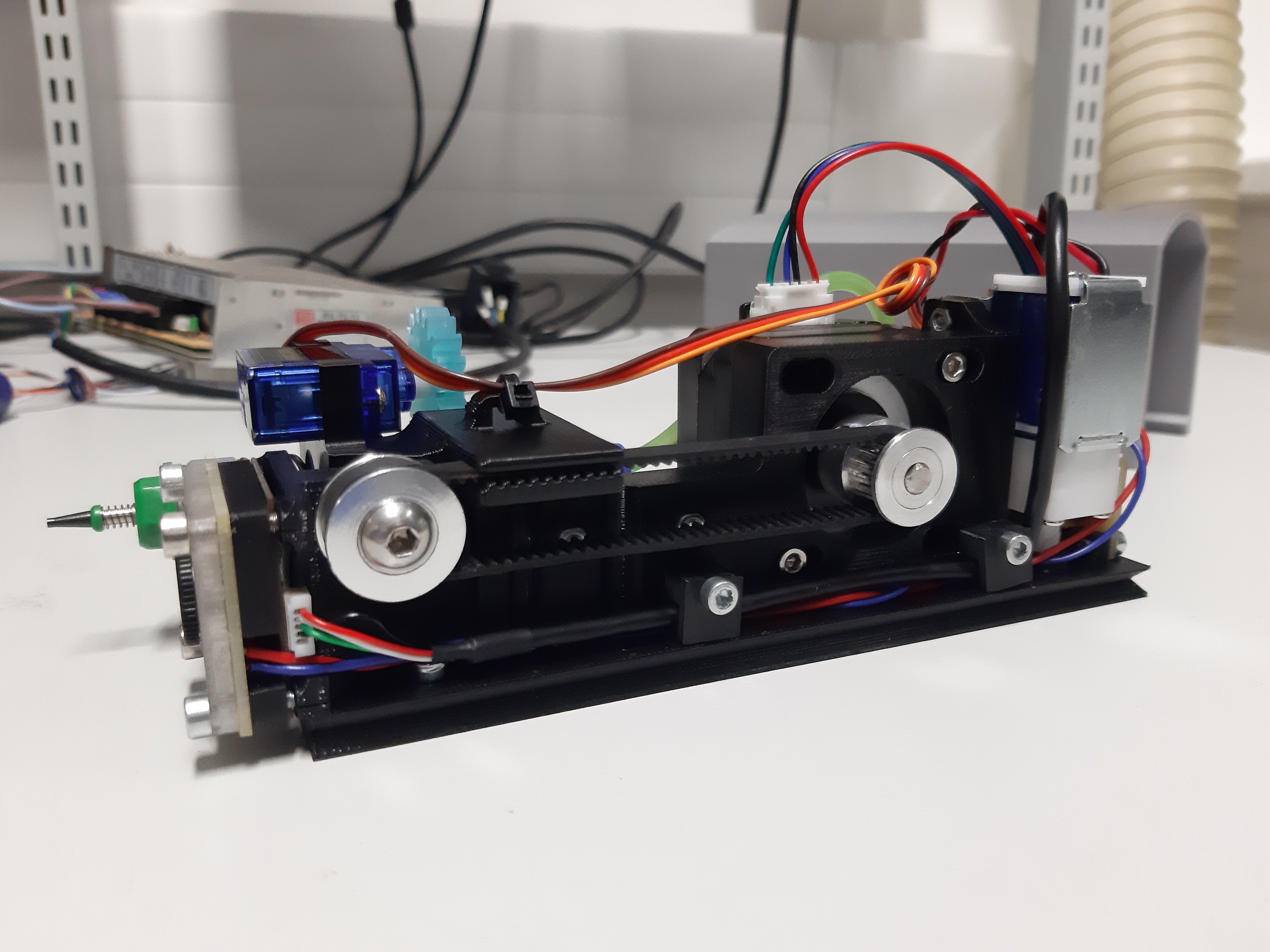
I prototypes head holder a lot. Again I took dimensions from Openplacer blueprints, but after few iterations I had to change some values so it is taller and bit wider that original design. Here is one of the first prototypes with long linear rail (I had no proper stepper motor at that time).
Endstop position testing and servo test with servo tester. Eccentric wiggling is because of smaller diameter of nozzle holder.
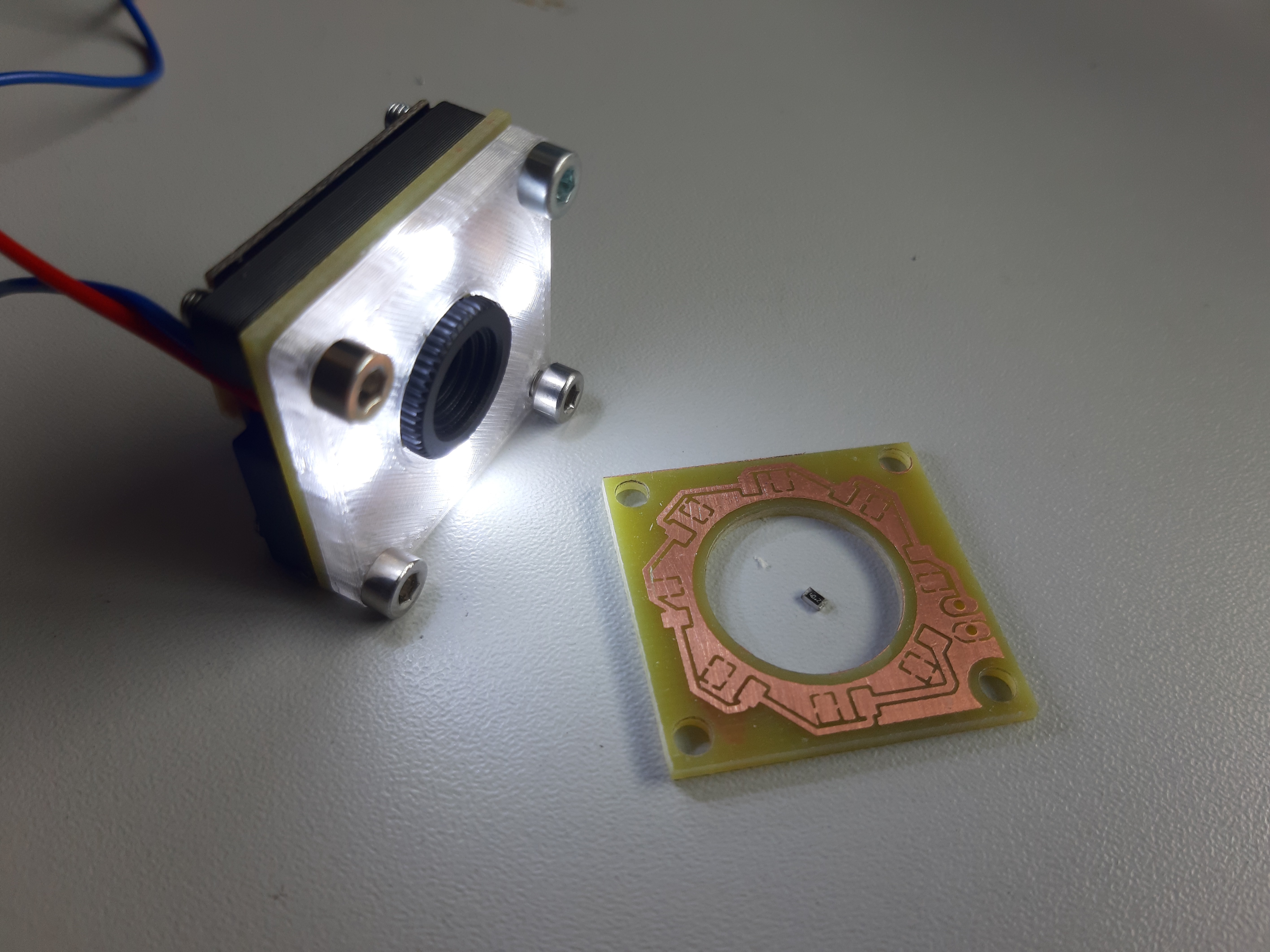
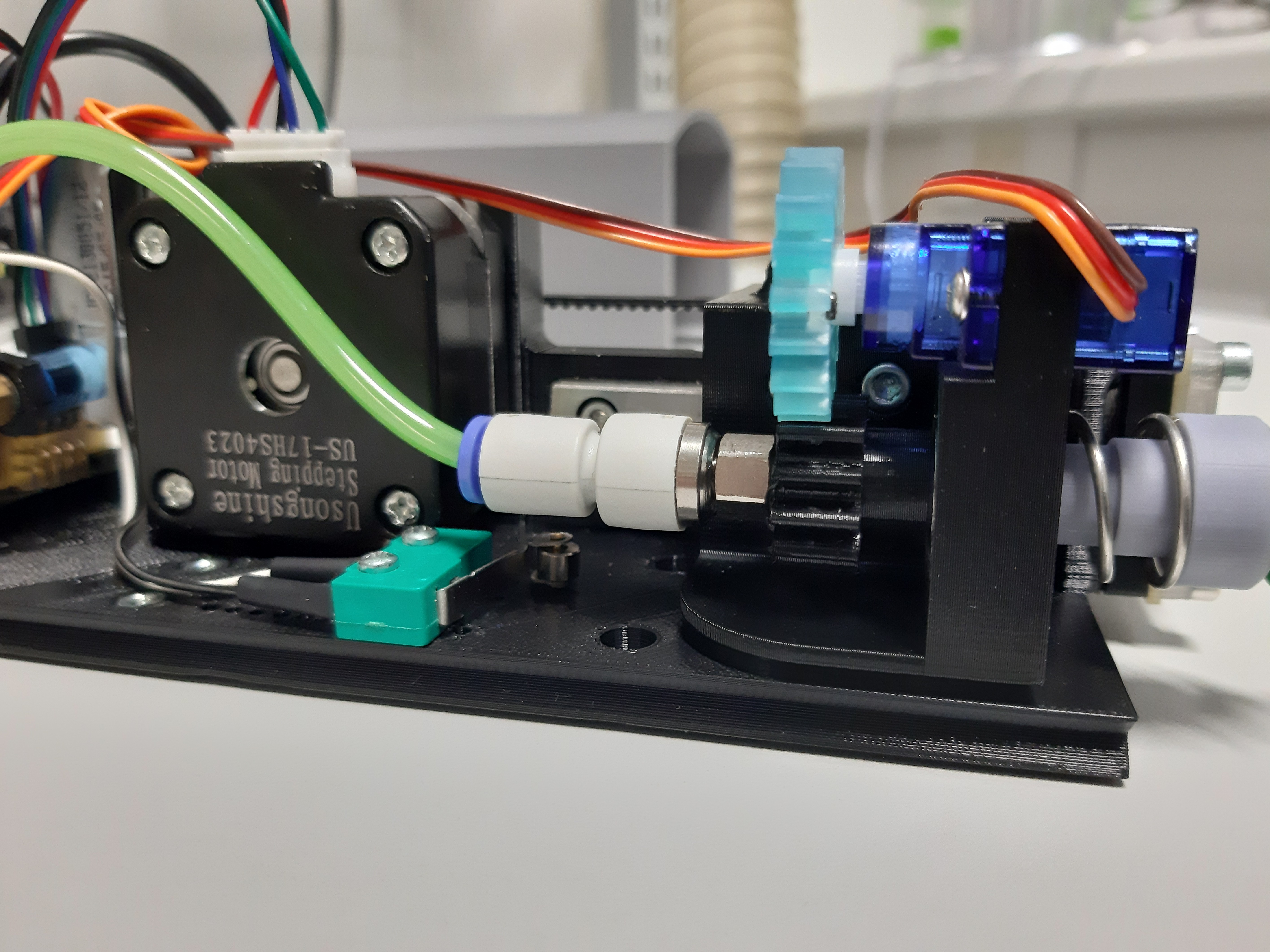
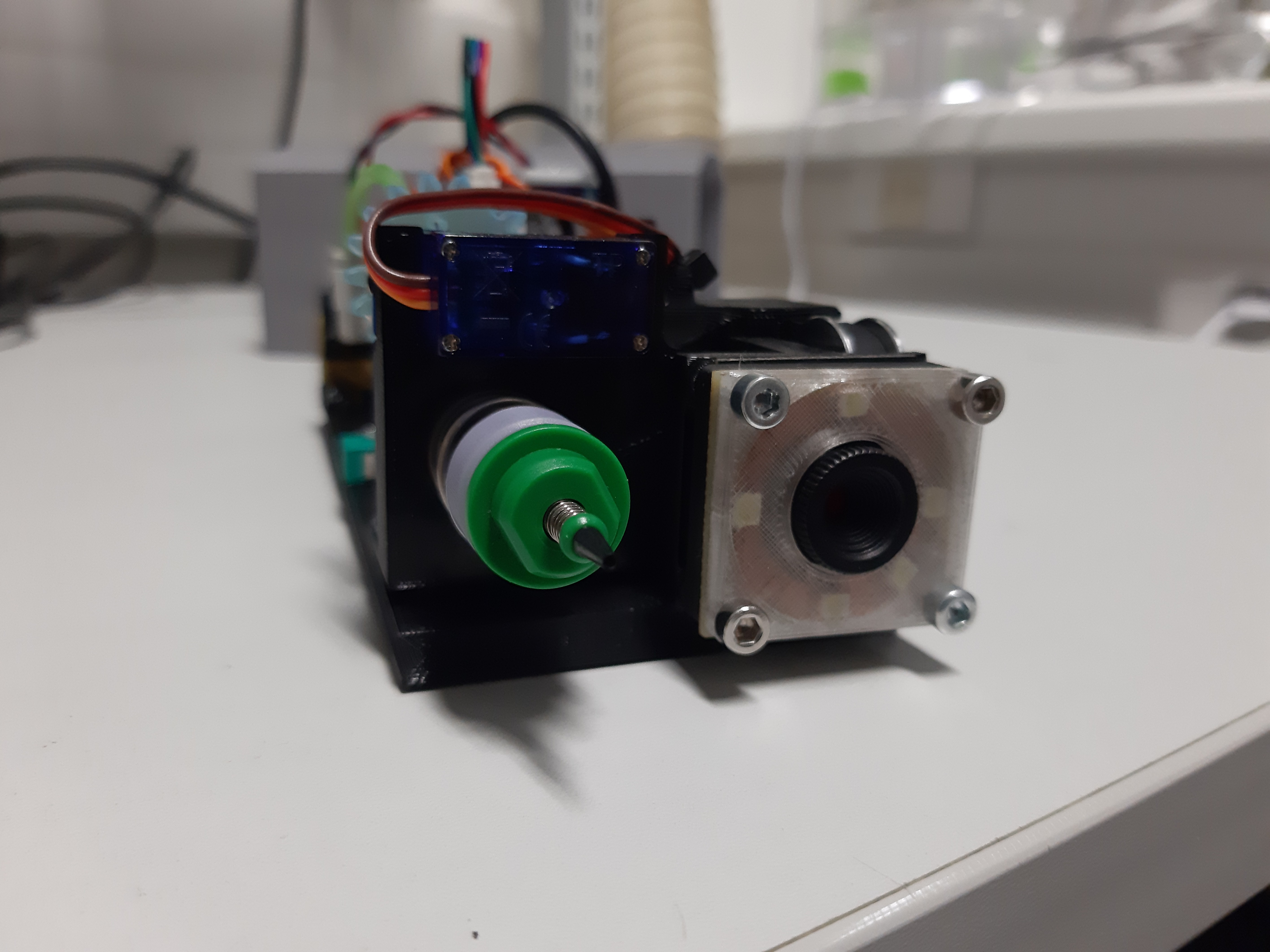
How you can see, head assembly it starting to shape. Stepper motor pull/push nozzle assembly up or down and limit switch is setting the home value of the Z axis. On this version of the head holder is still missing top camera. I use same top camera as Liteplacer project uses and I was also planning to use same LED ring as for bottom camera, but I could see in CAD that will be terrible big and it could collide with nozzle. Because of that, I designed small PCB with LED´s which will be sitting just underneath the camera. At the end, there is sort of sendwich of camera, printed spacer, PCB with light and printed piece which acts as diffuser. Part in the circle is 0805 resistor.
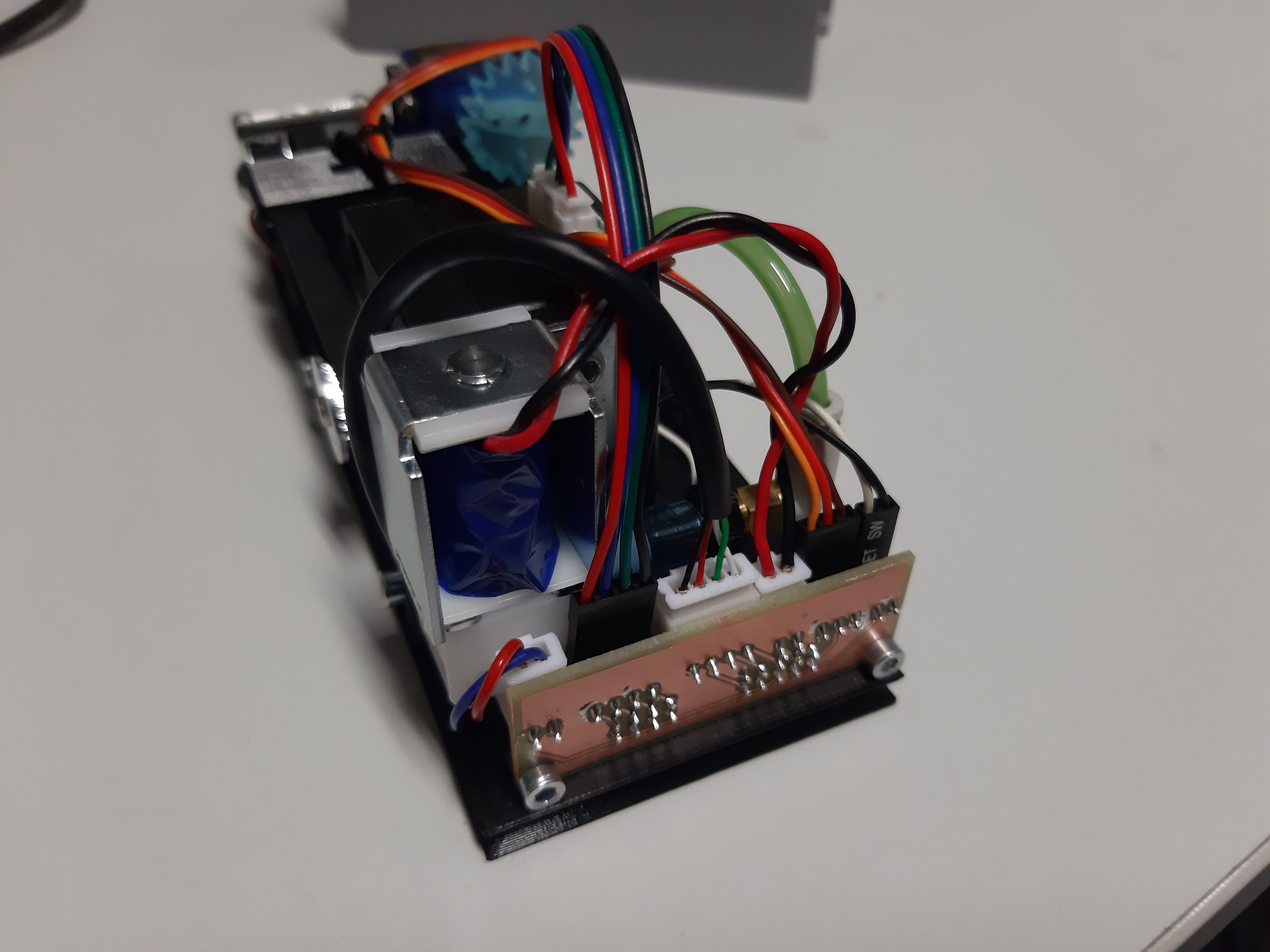
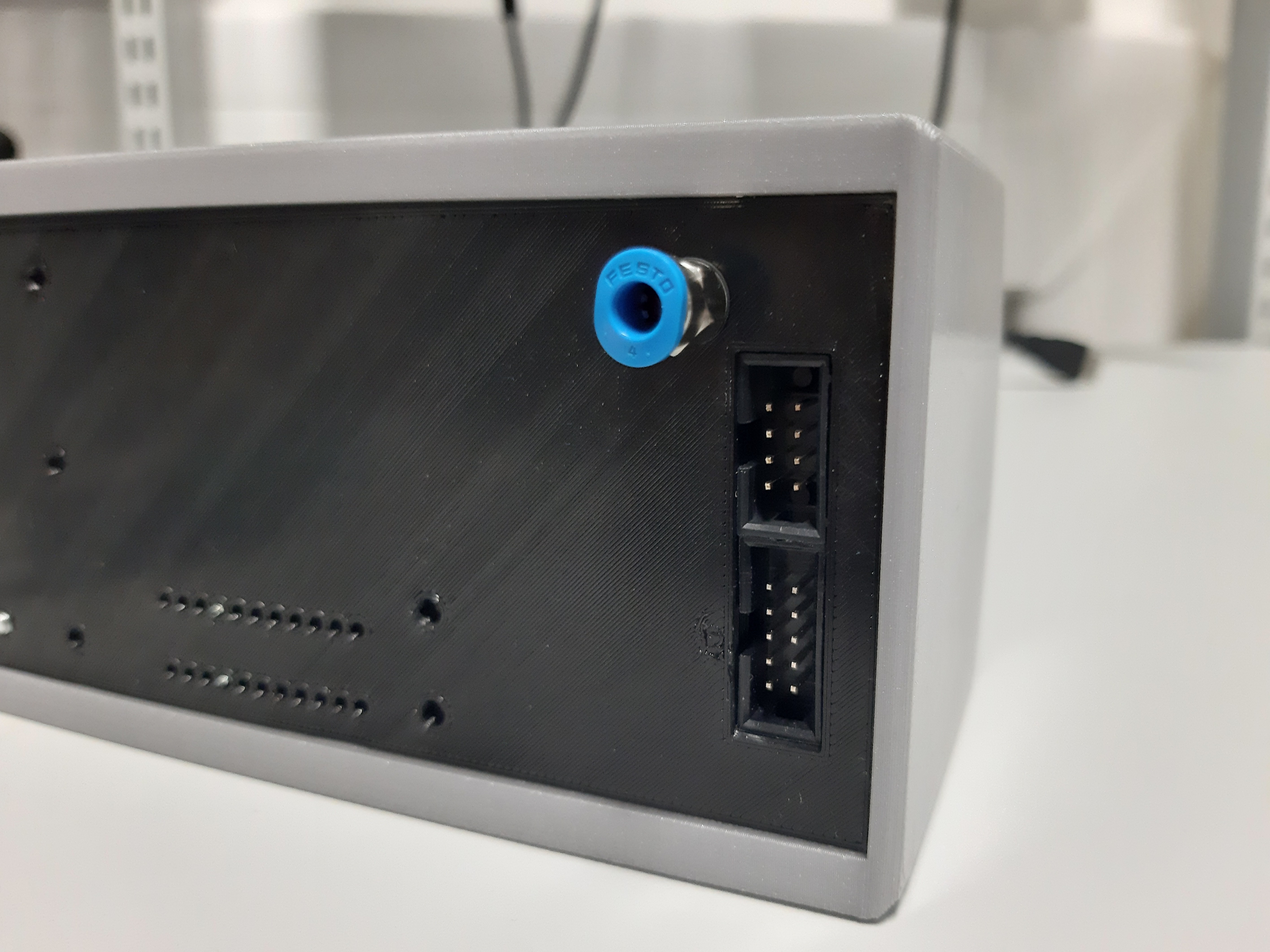
There are to more thing which need to be mentioned. Solenoid valve and PCB for connection to the board.
Solenoid valve which I ordered is normally open, that means air is still sucked through the nozzle and if you bring power to the solenoid, it will close itself and release the part. This mean, that you must have solenoid still at ON state and if you want grab a part, you will turn it OFF. I´m mentioning this as you will have to make sure that your device can handle more current (0.7A in this case) for long period of time. I ordered another valve which is normally closed, but I did not received this one yet.
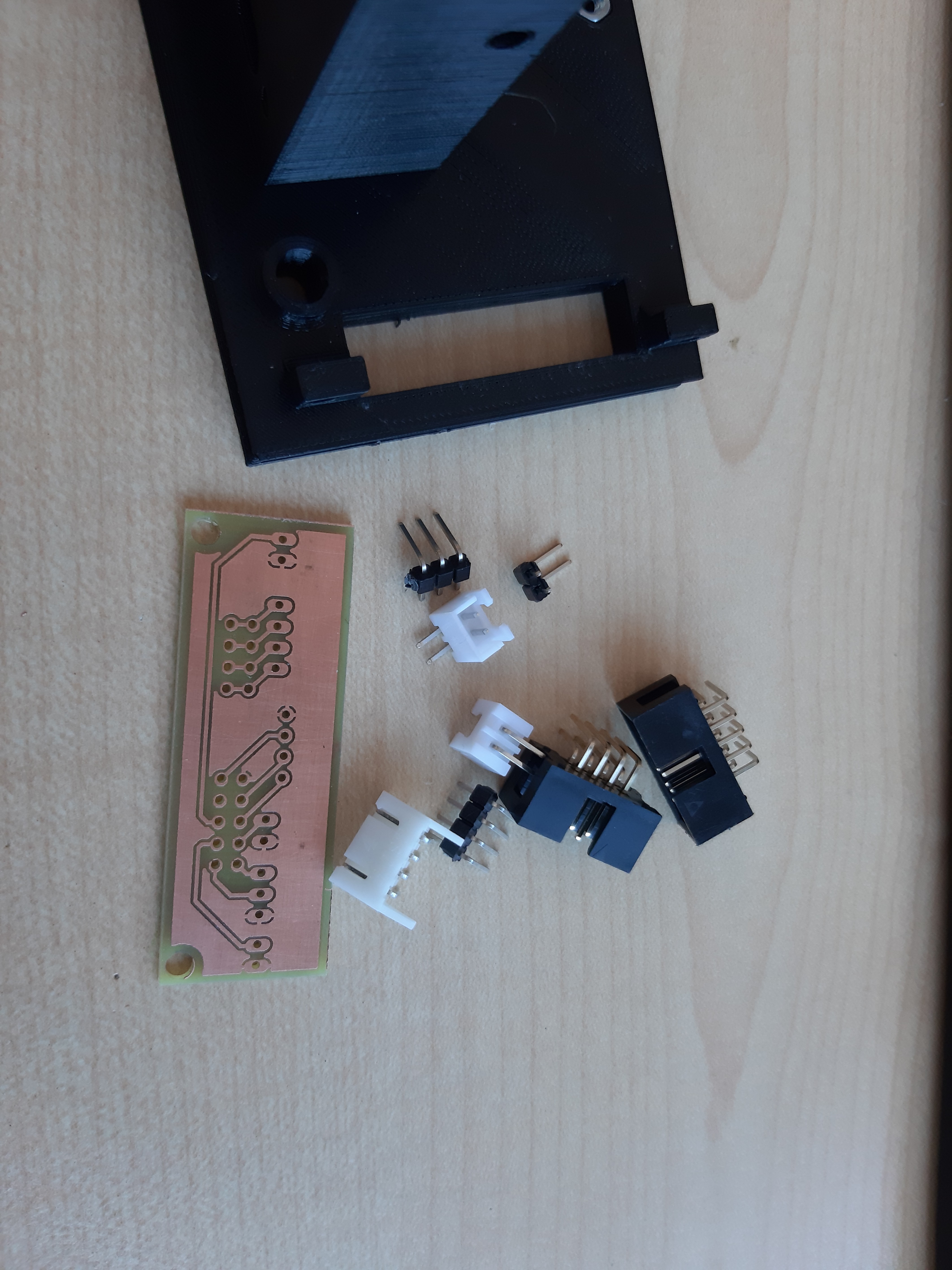
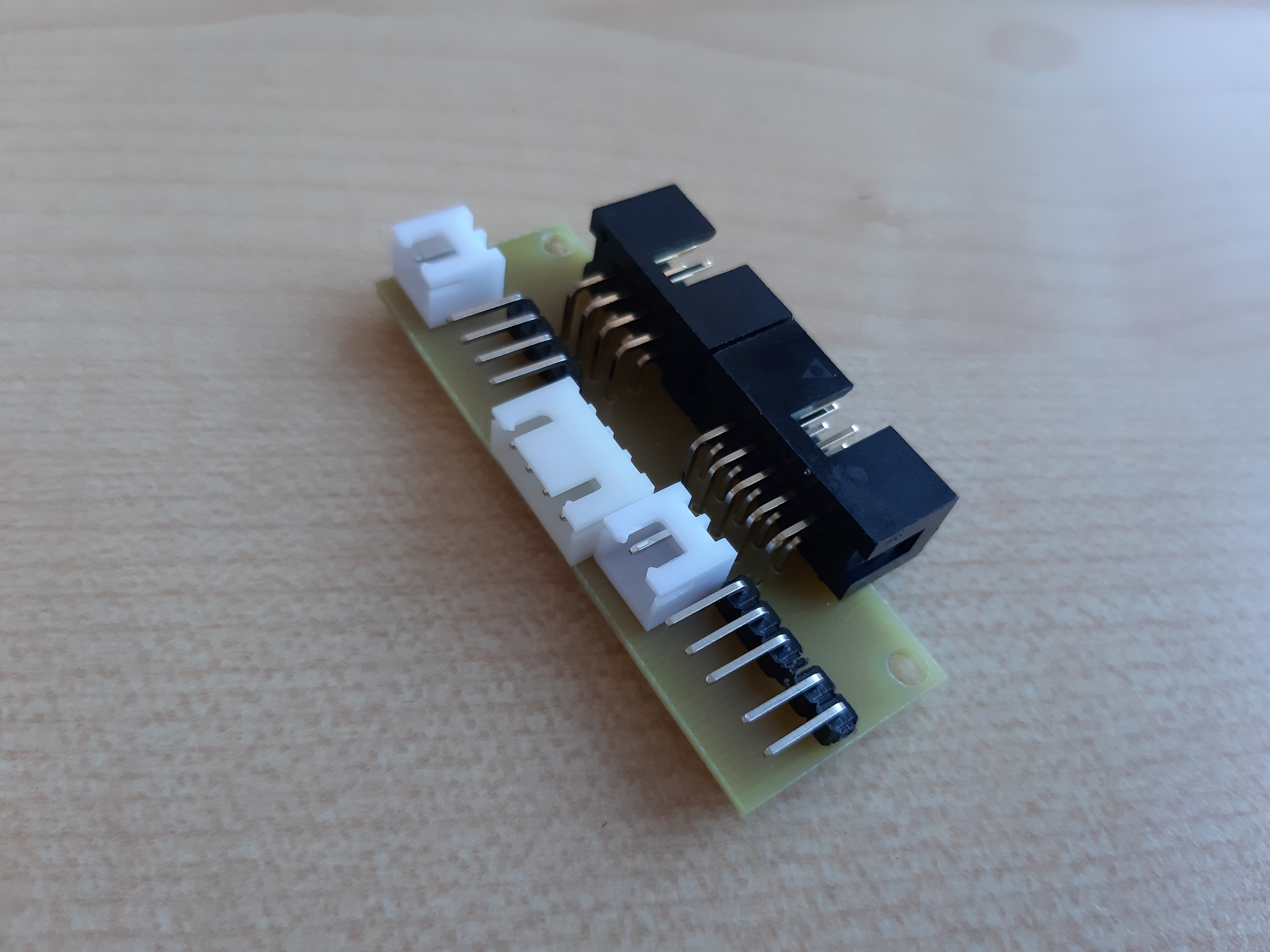
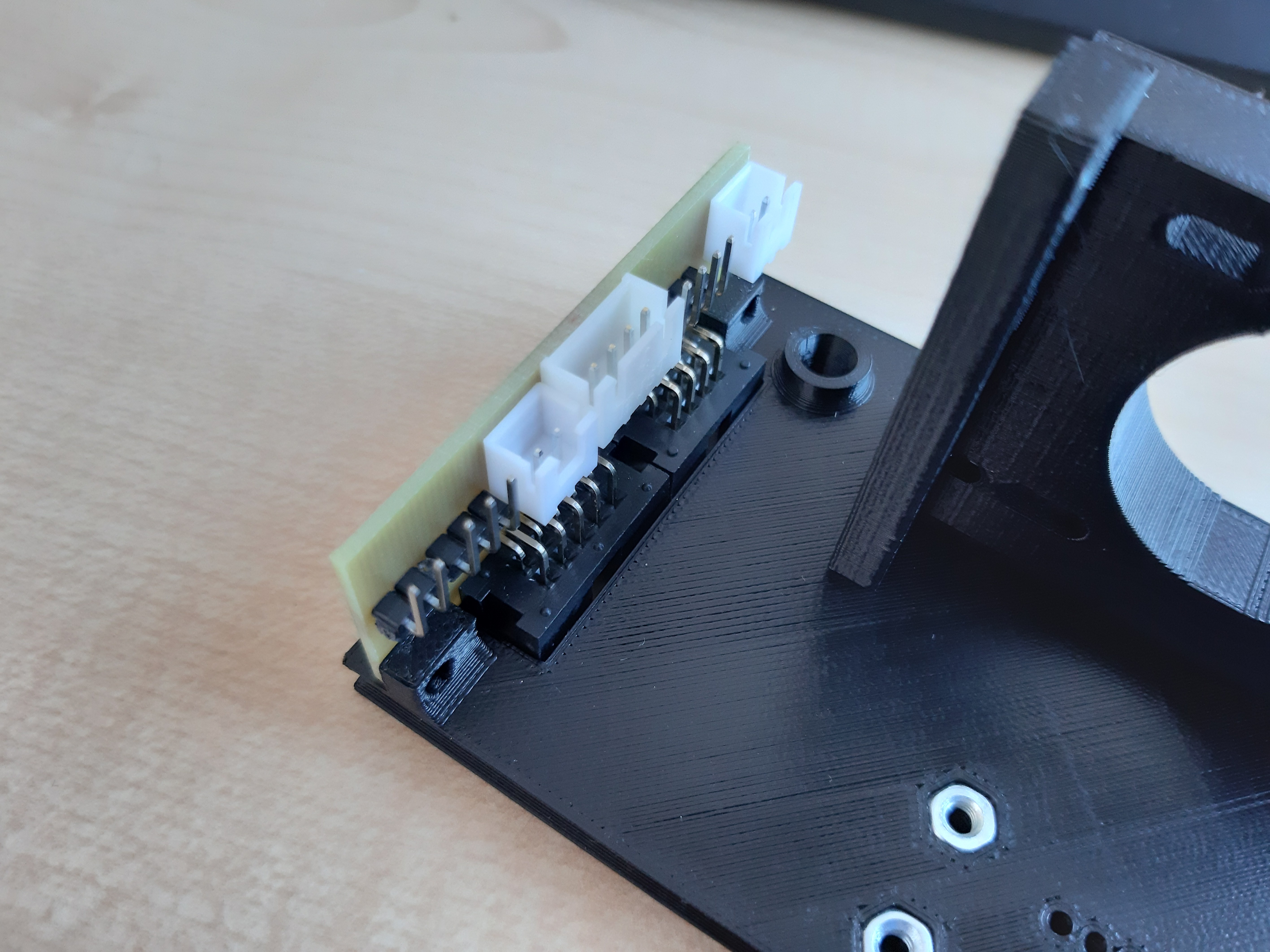
As i know that you have to make some repairs, whole head assembly should be easily dismantable, this include vacuum hose as well as cables. I was thinking about this already when I was designing head holder so I made room for it. This PCB unite all separate cables in two connectors.
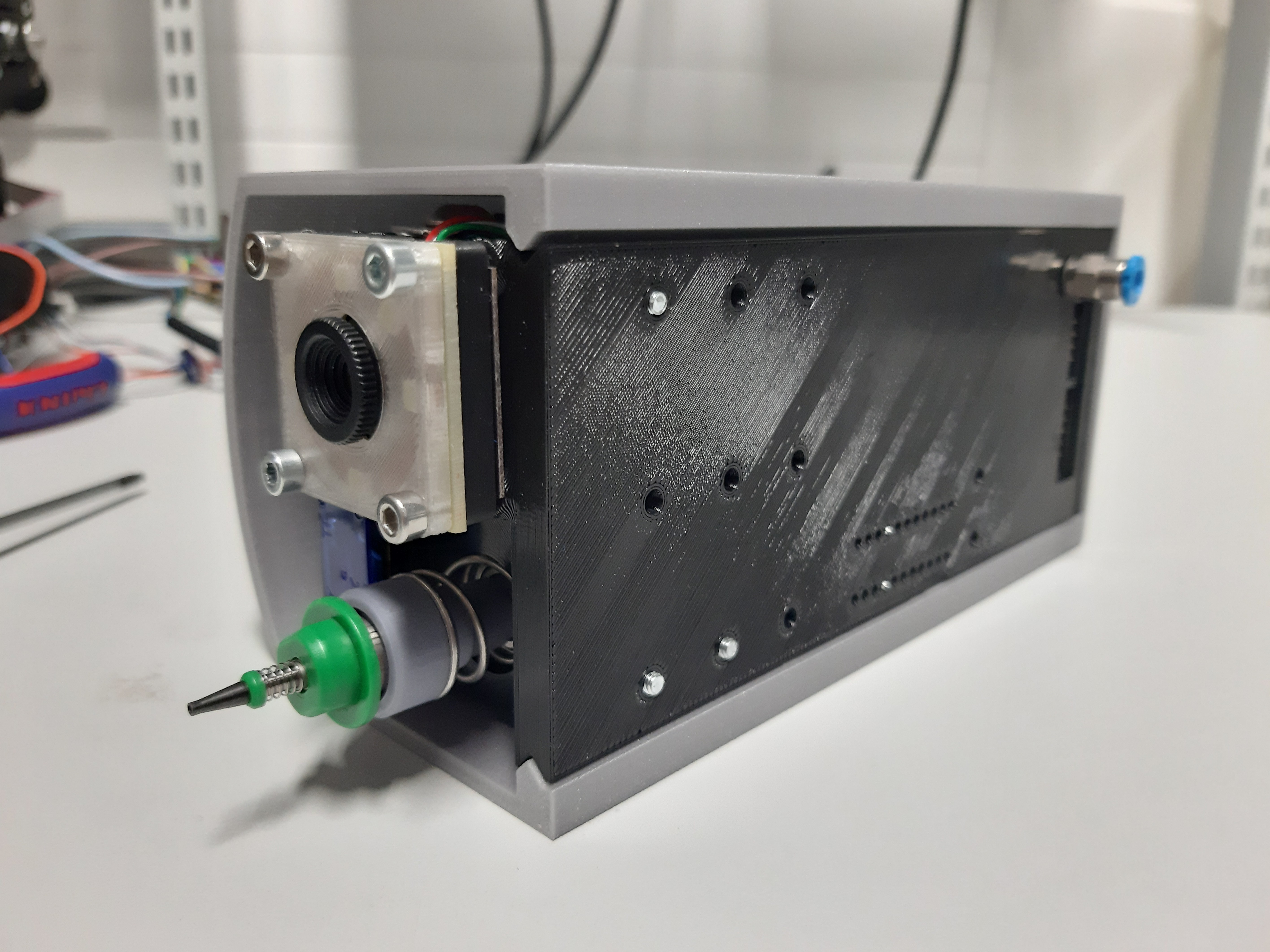
I finished whole assembly and here are pictures of it. There is also simple cover (you can see it in last picture), which will just slide on the head holder. I made for this, on side and top, triangle cutout which will drive cover all the way down. I will definitely make nozzle assembly with Nema 8 motors (with hollow shaft) when they will arrive, but I want to test this as I want to know if it can be used or not.
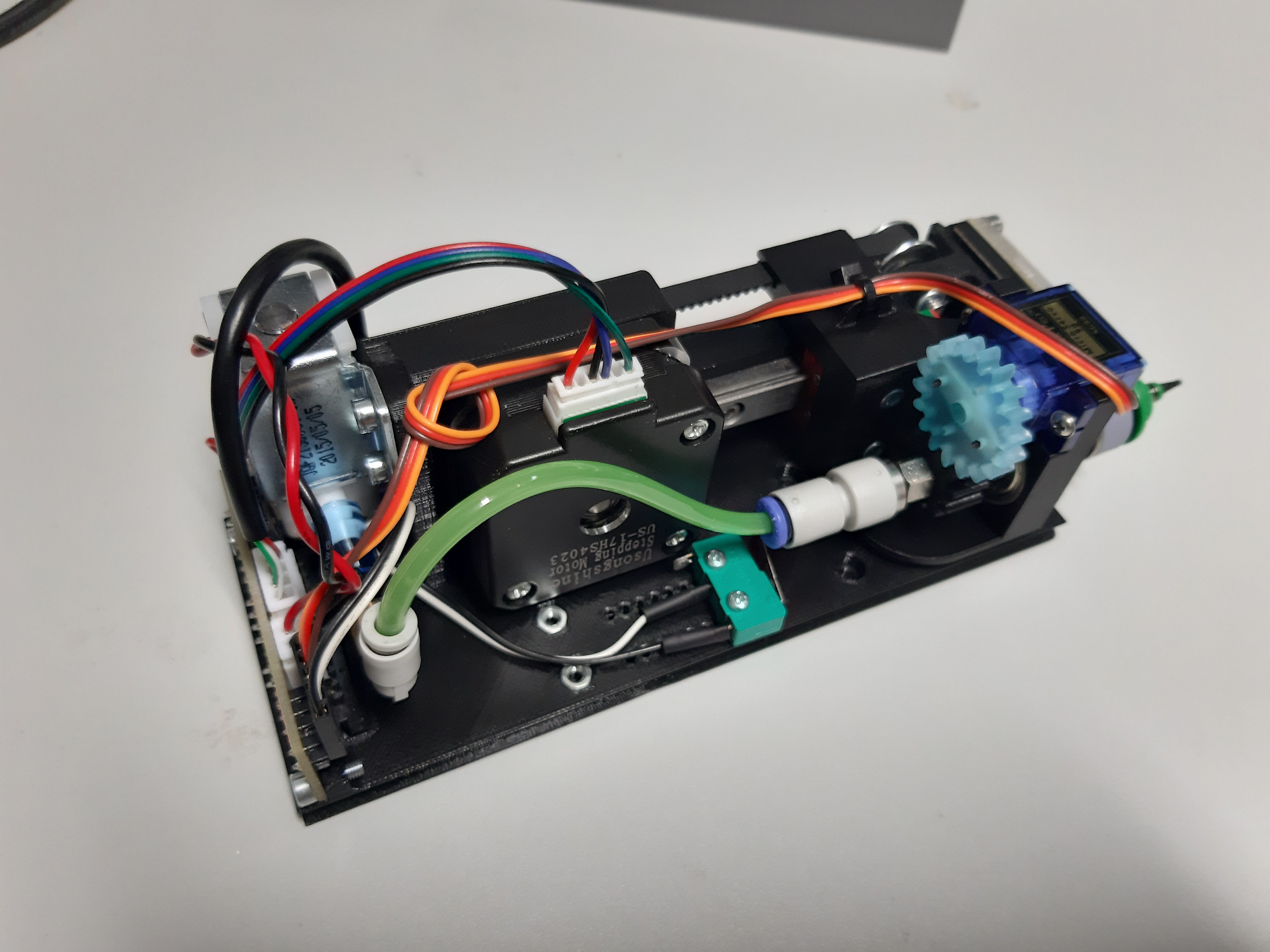
I have to finish cables from head assembly to the bottom of the PnP and test all it´s parts.
4) Body of the machine
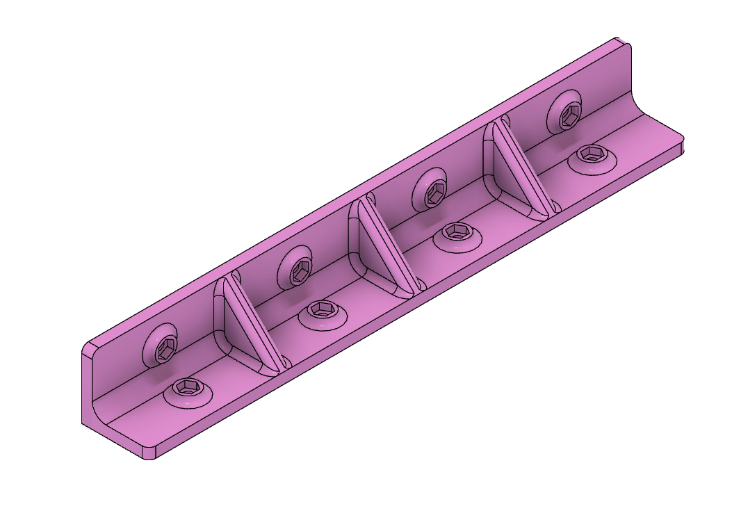
At start I thought that I will have same aluminium plate as Openplacer has, but for time of prototyping I´m using sheet of 3 mm MDF. It is not strong but it is cheap and it can be easily cut by hand or on laser cutter. I was also planning that I will have sides from 1 mm steel plate with bend edges which will connect to top and bottom plate, but again that would be hard to prototype as you can not (mostly) make it at your workshop. Instead I designed parametric L shaped corner brackets which do the same and I can print them.
These pieces are connecting top plate to the side plates, which are now combination of 3 mm MDF and 3 mm acrylic. Because of parametric design I can change one value, if I need to, and I can make it from more thick material.
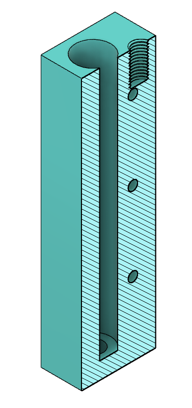
I was also planing to use these corner brackets to connect side plates together, but I found out that I will not have enough room for screws which holds front and back pieces of Y axis to top plate, so I designed different piece which goes from top to bottom and has holes for these screw.
At the end, top plate will be 5 or 8 mm acrylic, so I hope that will make body strong and rigid enough, and if not I can order aluminium plate with already tested holes.
I´m working on this for a 3 months or so and here is what I have so far:
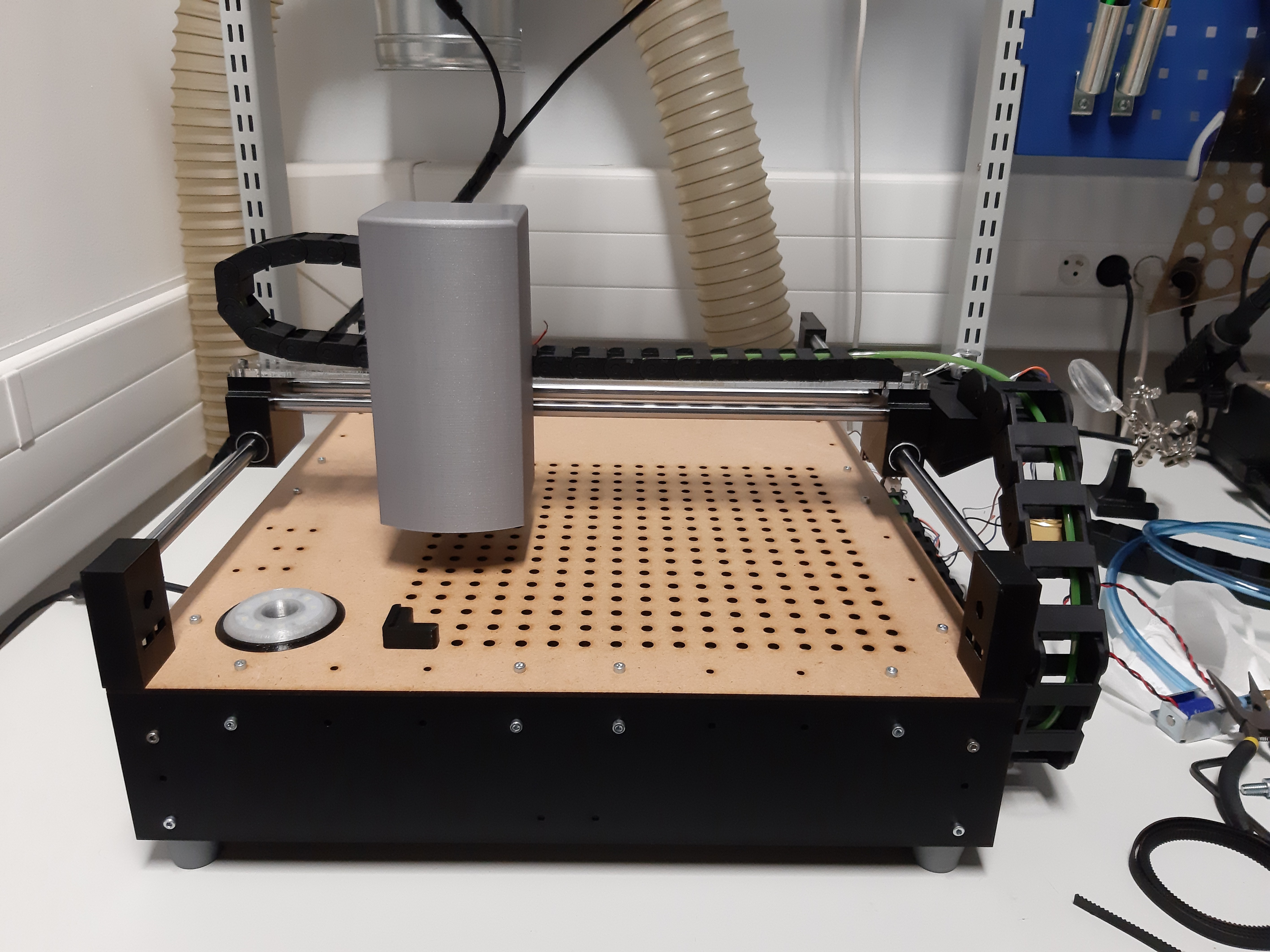 Next step will be installation of all components inside of the machine and test of all kinds.
 Stay tuned if you like it so far.
Discussions
Become a Hackaday.io Member
Create an account to leave a comment. Already have an account? Log In.