 Alex Dunnett
Spherical Drive Systems!
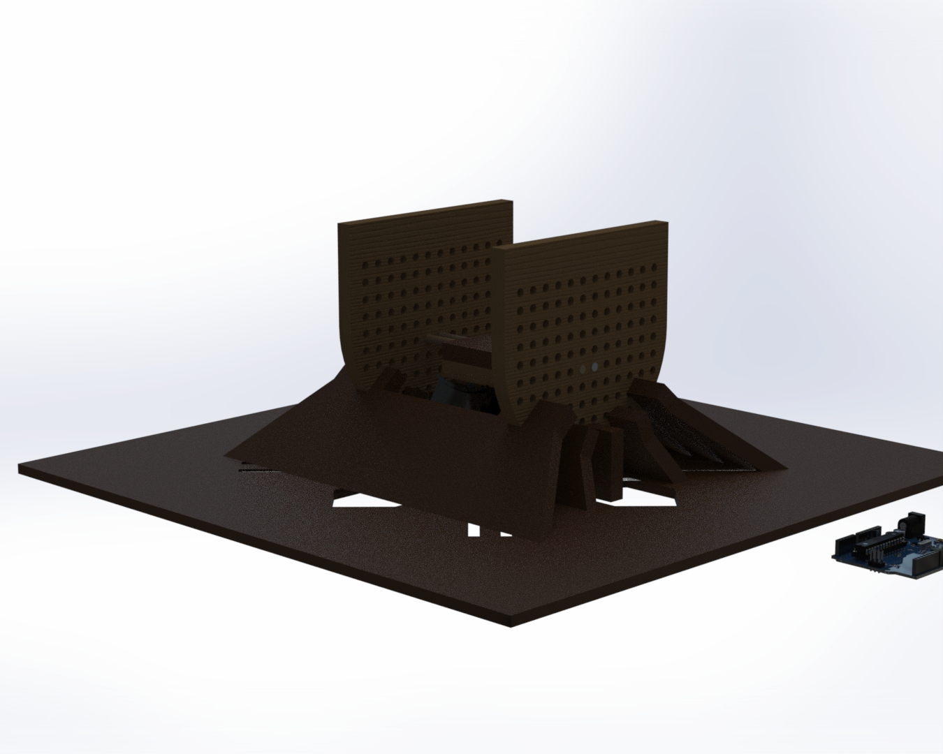
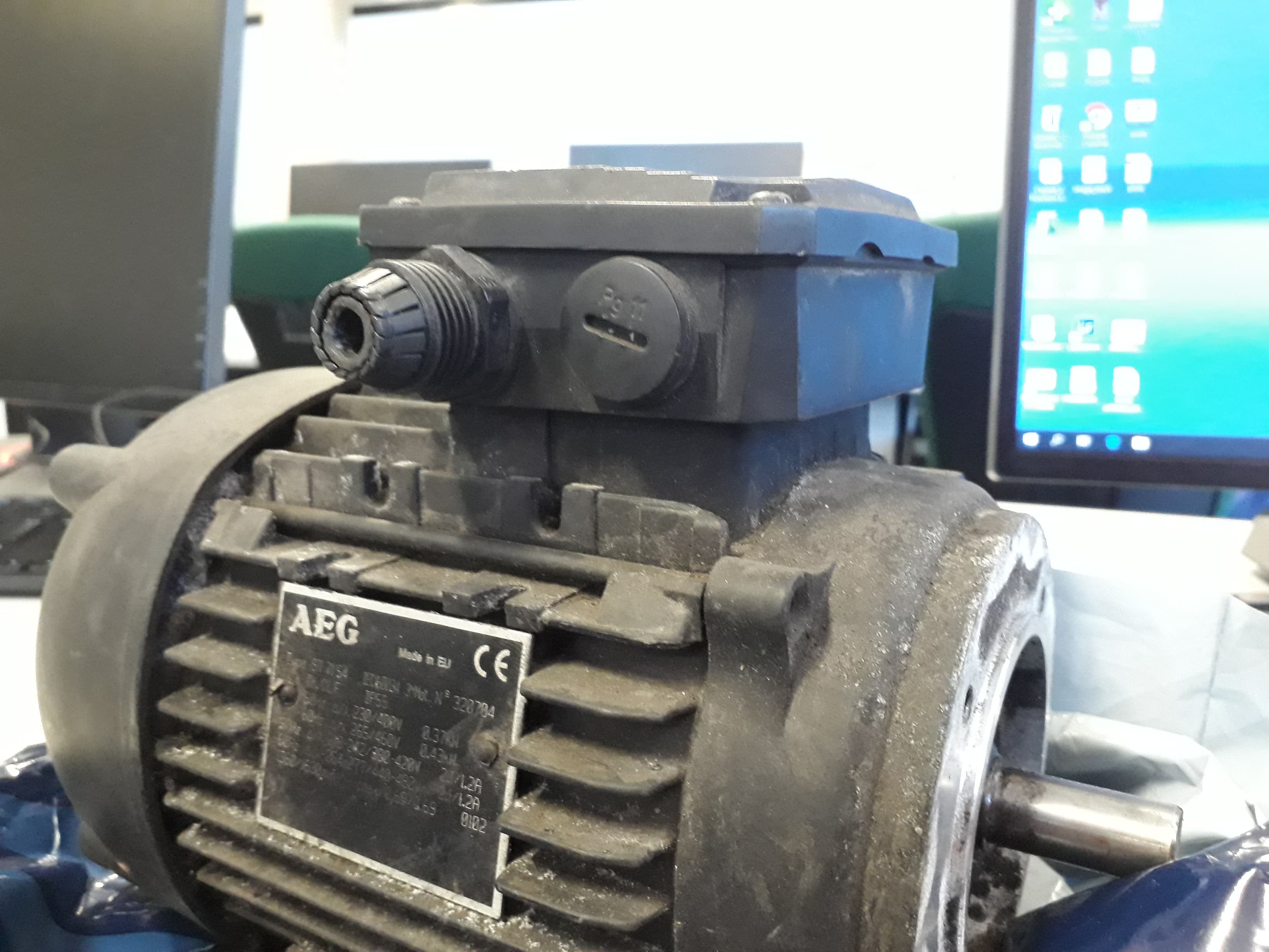
After spending the first couple of months of my project researching and theorizing I decided to attempt to develop two prototypes, time permitting. One being a simple cylindrical rotor motor mounted onto a curved linear induction stator in order to prove the concept, and the second a fully fledged spherical drive system.
So how does it work?
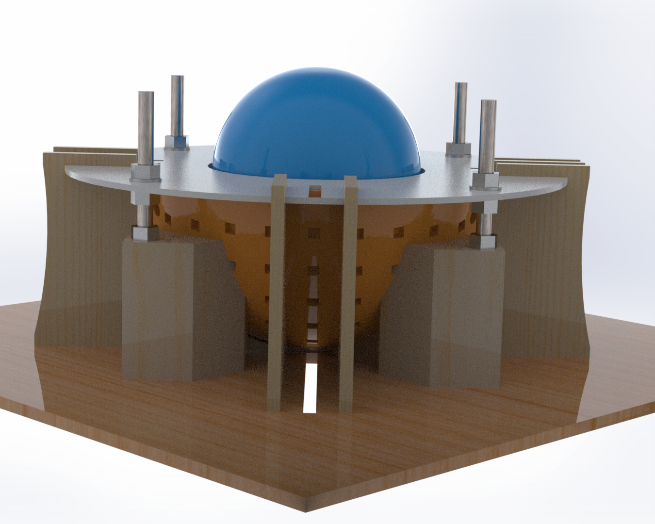
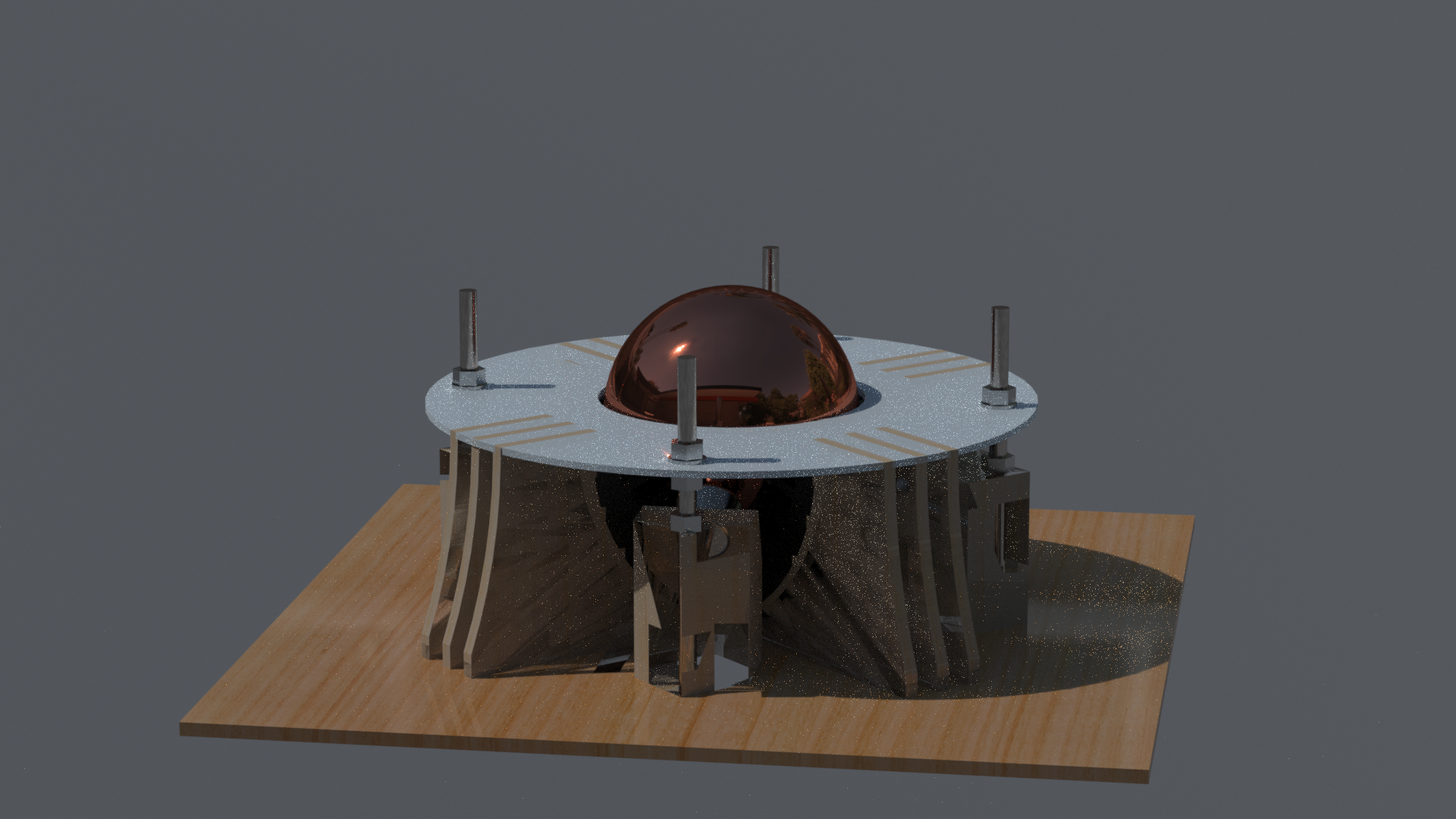
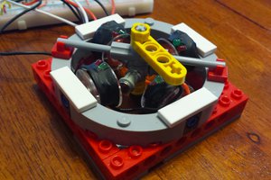
Well, the aim is to ultimately end up with a ball (rotor) that is powered externally by the socket (stator) in which it is placed. This will hopefully be achieved through the use of phase shifted AC current (mimicking conventional 3 phase power) to induce changing magnetic fields around the stator coils. This will induce a back-EMF within the copper shell of the rotor as well as a reactionary magnetic field. The two magnetic fields should interact and generate a torque upon the ball/rotor.
The thinking here is that if this works then multiple stators in different configurations could be used to provide different torque vectors and, before you know it, you'll be sliding your tesla into that tight space and guffawing that anyone had ever seriously considered doing a parallel park.


 Adam Smallcomb
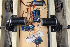
 David
David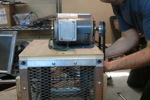
 Scott Swaaley
what software do you use for simulation FEM?