 Alex Dunnett
Lots of progress :)
Design
Design has been finalised, with changes only to be made for tweaks in manufacture.
The plan is to produce 3 separate devices that can all be assembled on the same rig. i.e. they are all modular devices.
Device #1: AC Induction Sphere:
Stators: 4 Perpendicular Stators
Rotor/Sphere: Hollow steel sphere with copper shell
Coil Excitation: 3 Phase AC
Rotation Mechanism: Stator magnetic field interaction with eddy currents in rotor shell.
Device #2: BLDC Sphere
Stators: 4 Perpendicular Stators
Rotor/Sphere: ABS Sphere with 187 Neodymium magnet [N52] studs
Coil Excitation: Pulsed DC
Rotation Mechanism: Stator magnetic field interaction with Neodymium magnet studs.
Device #3: Flux Measurement Device
Stators: 1 Stator
Measurement Device: 10 Hall Effect Sensors on a breadboard
Coil Excitation: 3 Phase AC
Measurement Mechanism: Position Hall Effect Sensors around rig and measure the flux the magnetic flux strength.
-BONUS DEVICE: Old AC Induction Motor -
Went looking around for coils and stators at a motor repair shop in Sheffield and came across this beauty.
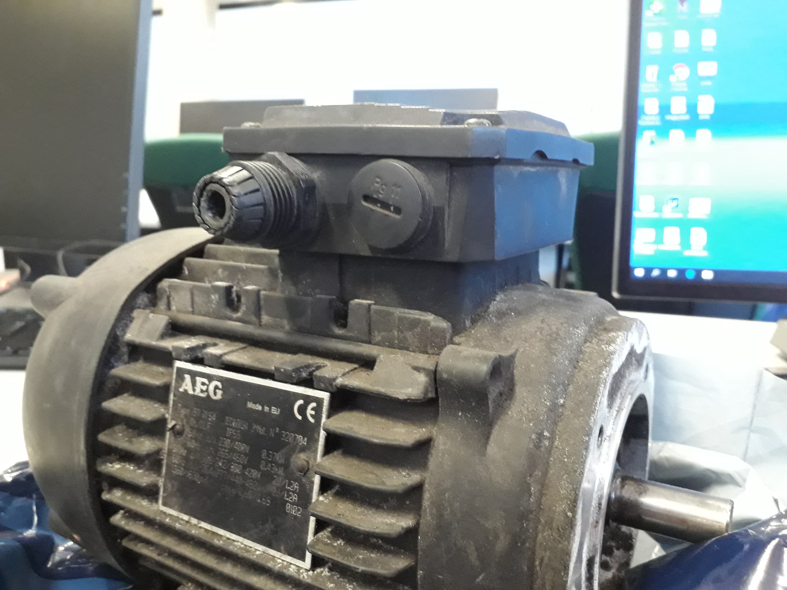
Took the seized bearing out and will connect up my power supply soon. This should determine if my power supply is suitable in its current form.
Power Supply
Basically *fingers crossed* fixed! By using the Arduino Mega and 3 Motor boards being controlled separately I was (after sometime) able to produce 3 phase AC current. The big issue was powering all 3 motor shield processors from one Mega, the problem was compounded when one of my solutions caused a motor board to start smoking. I figured the cause of this may have been that I was still missing a pin in my wiring set up (Shields are supposed to be connected to all pins on an Arduino Uno). To remedy this I placed the shield on an Uno but connected the relevant pins to the Mega. This appeared to work as intended :D.
The Steel Solution
I have accepted that with my budget the only way to progress is to just use regular mild steel sheet for my stators (and steel sphere sections). Hopefully this could still give me relative permeability values of around 1000 (which is pretty good), but I am prepared that I may get much lower values. The lack of knowledge as to what values I would get has lead me to propose the flux measurement device so that I can lump all parameters into a single parameter. i.e. how strong is the magnetic field that actually gets produced.
Dilemmas
- Steel is expensive!
I have been forced to reduce the wall thickness of my sphere so that i can fit my sections within other sections. Turns out Halos do not make the most efficient use of space and I really don't have an awful lot of budget left.
- Forced Dimensions Changes -
After finding a pre-built copper shell (from a 4.5" float valve), which was always going to be the hardest thing to manufacture myself, I needed to scale up all of my designs to accommodate a 115mm rotor rather than a 100mm rotor. This is very doable though it means that my previous work in the IForge goes to waste :/
- Coil Windings -
I have definitely not given this as much thought as I should have. My current plan is to use a dLRK winding scheme ( as is currently used by hobbyist aircraft enthusiasts, and the connect the wires together using a star/delta arrangement. I'm going to talk to the uni electronics guy tomorrow so hopefully he'll say what I should do.
- Sensors -
With the various arduino power supply concerns I have not really spent enough time setting up my sensing rig.
The sensors to be used will consist of
- On-board Current Sensing from the Motor Shields. As these are already connected to the Arduino UNOs, I should be able to access the current data very easily indeed. The Arduino "Serial.print" function does not have the ability to print to file. However I can include the relevant clock cycle of any reading, making provisions for the delay between the printing of the clock cycle and the printing of the data, and copy/paste the data from Serial.monitor.... Though currently CNTL C/V isn't working too well. - May be able to use a third party software such as Putty or Hyperterm.
- Hall effect Sensors to sense the Magnetic Field Strength, same method as before in terms of copy/pasting off of the Serial monitor with the relevant clock cycle/ time stamp. Need to work on calibrating those sensor readings. - I might be able to do this by using the neodymium magnets which supposedly have a rated magnetic field strength (~1T).
- Speed Measurement - This is going to be harder. For the BLDC sphere I may be able to use a hall effect sensor to detect the passing magnetic studs. For the Induction sphere I'm going to struggle. One possible solution would be to paint two circle loops in different colours around the azimuth and elevation axes and just count their passing over a period of time. If I had two sets of power supplies I would be able to prove that the angular velocity would be a superposition of the angular speeds around each axis. Sadly that would be too expensive :/
Next log should pretty much just be manufacture and me being my told by the university that my electronics are not safe enough in their current form. :P
in the words of Phil Collins, "That's all"
Discussions
Become a Hackaday.io Member
Create an account to leave a comment. Already have an account? Log In.