 MS-BOSS
Have you ever had the need to sample some analog signal? If so, it was probably at low frequencies. Quite probably some audio grade stuff. Everyone knows how to do that. Either take a complete sample-and-hold amplifier like the old LF398 or the DIY way by connecting together some generic amplifier, capacitor and some electronically controlled switch like the 4066.
But what if you look a bit higher? Several megahertz and up? Okay, the 4066 method still may be useable. You can find quite a lot of receivers which use a 4053 or 4066 as an IQ demodulator for short-wave amateur radio. Still good, still cheap and simple.
But the true question is what happens once you want to sample something which extends beyond several hundred megahertz or even several gigahertz. Then you will find yourself in a very uncomfortable place. If you wish to do some voodoo with OTAs, you can reach hundreds of megahertz, but for more you have to dive into your pocket and look very deep in your pocket. First, you will be shocked because there are only a few parts which can do such things, like the HMC760. But seriously, are you going to pay $360 for a chip? Maybe, but not me.
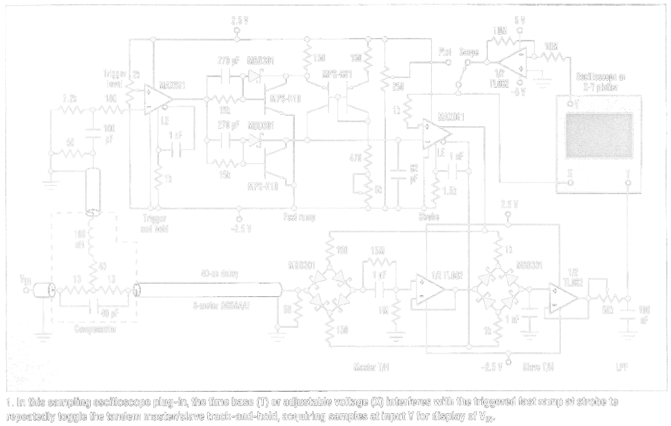
Okay, so searching at e-shops answered the question showed us there is no part which would do this job for us. Time for diving into old manuals, schematics and articles! Maybe some of you have already met some old TDR machine or a 60s Tektronix sampling oscilloscope. They usually have quite similar sampler. Some are very simple, some are very intricate. But the principle is always the same - using diodes as sampling bridges. When current passes through them, so does signal. Turn off the current and the signal also stops going through. Ideally, that is.
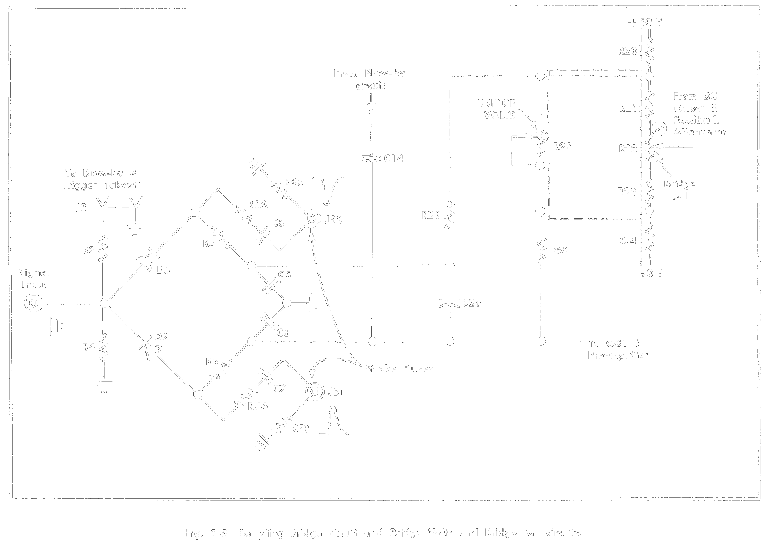
What you can see on this part of schematic form S-2 sampling head is the sampler. It doesn't look obvious, does it? If you don't believe it is a sampler, read the manual which explains the whole sampling head and each of its parts, how it works and how to make it work. It's sad you don't get a manual like this these days. Note that this sampling head was introduced in 1967 and offered 4.6 GHz of bandwidth and <75 ps of risetime.
To summarize it: a very short pulse of current of defined length goes through the diodes, turns them on briefly and then turns them off again very fast. The two key parameters here are how fast you can turn off the diodes and how precisely you can control at what time it happens. Let's look at how the folks at Tek did this magic.
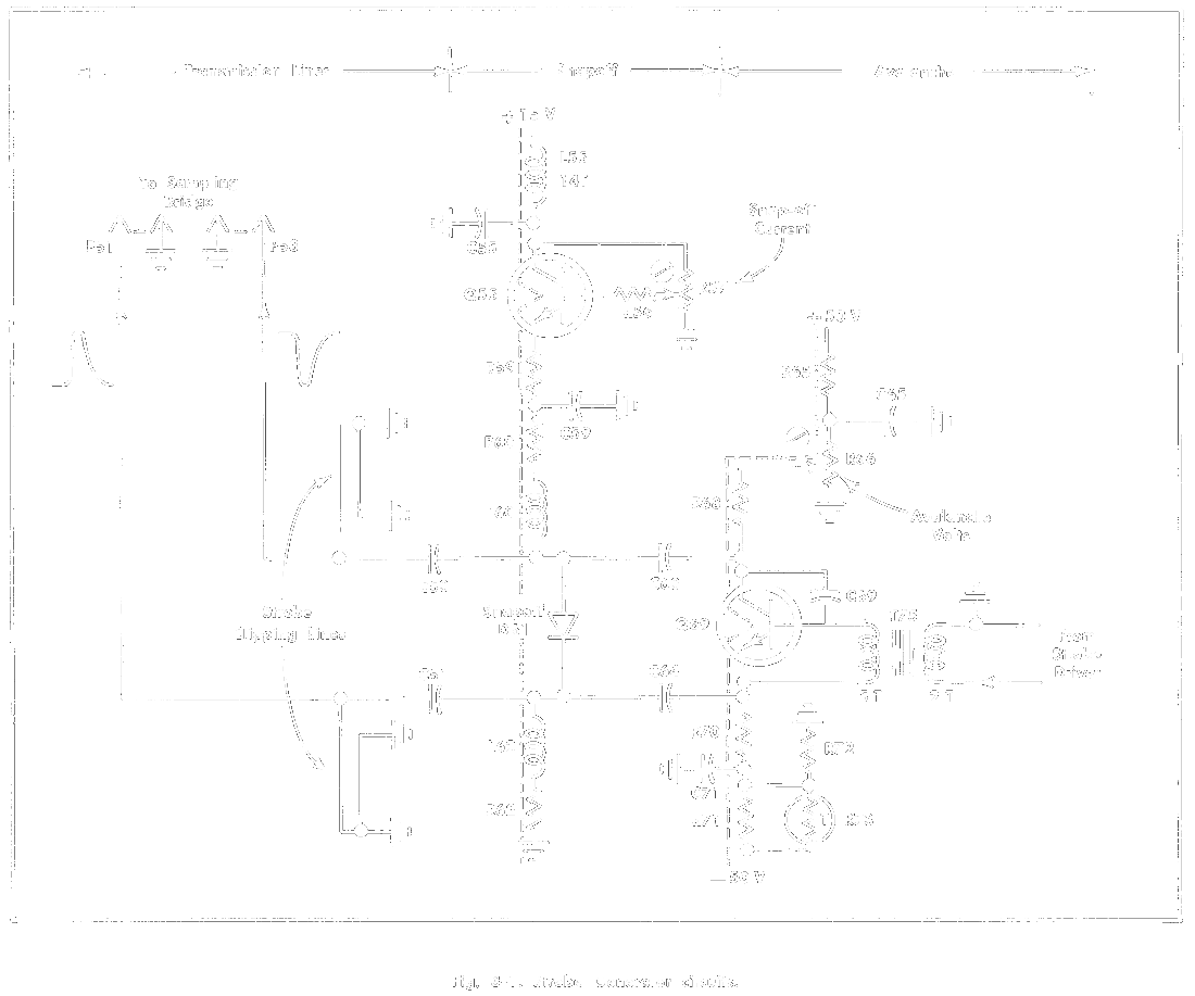
What you see is an avalanche pulse generator. You may have already seen it in one of my projects. Essentially it is transistor which has collector-emitter voltage so high it almost goes into avalanche breakdown, but not on its own. The avalanche is triggered by other circuitry using the transformer on the right. This makes a very fast pulse. To make it even faster, a snapoff diode is used (these are very hard to come by these days). The length of the pulse is precisely set by the two "cliplines" on the left.
It is fast and great, but it requires several supply voltages (and quite high!), draws a lot of current and cannot be triggered very often, because it has to reach steady state again. What about doing it less complicated?
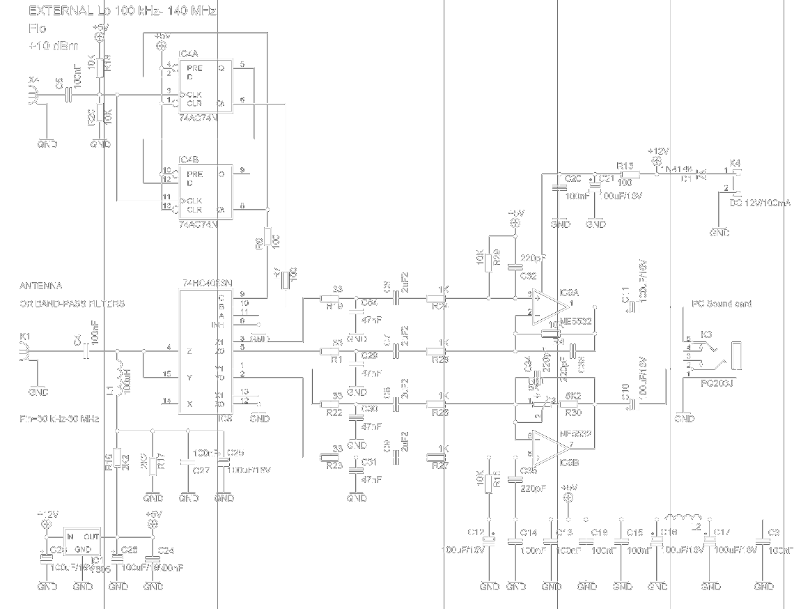
If you look at article by Hubert Houtman, you can see that it is possible to achieve about 1 GHz of bandwidth using just a "quite" fast comparator and two resistors.
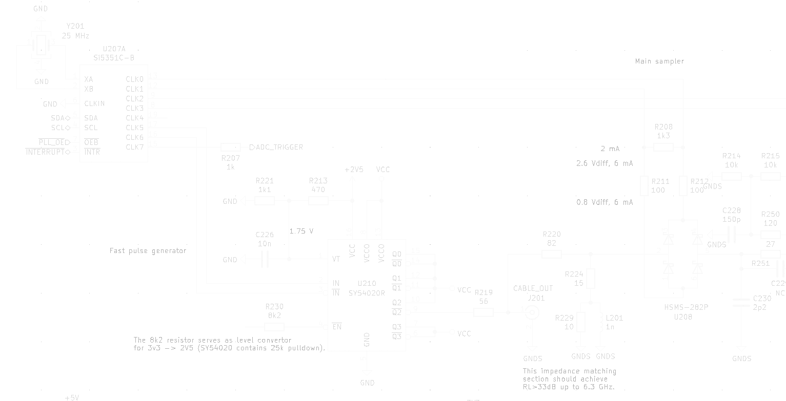
The MAX961 comparators have rise/fall times about 2.3 ns. The outputs of the Si5351 have those times under 1 ns and are implemented as current sources. Theoretically, this could get us at least 2 GHz of bandwidth using the same diodes. Since we can get faster diodes today, it could be even better. The only unpleasant side effect is a need for a virtual analog ground at 1.65 V potential (half the 3.3 V supply for the Si5351).
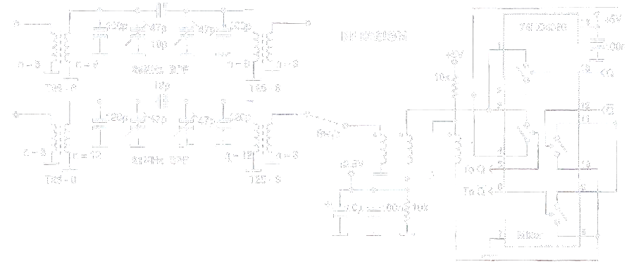
To see how simple it can be, look at the lower right part of the next image. Four diodes, three resistors and directly connect it to Si5351. Nothing complicated. The result is about 200 ps of measured risetime from generator with 85 ps risetime.
Discussions
Become a Hackaday.io Member
Create an account to leave a comment. Already have an account? Log In.