 Bud Bennett
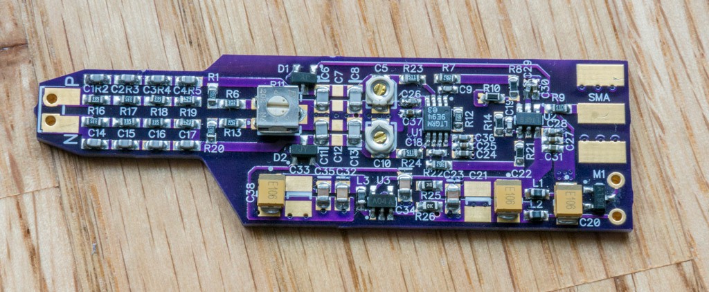
PCBs and components arrived within a day of each other. I had the first prototype assembled and working in an afternoon, with some compromises: I used 3.6kΩ/390Ω resistors for the first gain stage instead of 3.92kΩ/412Ω, and I don’t have any SMA connectors yet, so I can’t tie the output directly to the scope input. So the gain is 3% low.
Power supply current = 52mA.
First thing I checked was the ground supply to make sure that the M7301 opamp was not oscillating — no buzz. I did not populate the 22µF ceramics at the input and output of the LM7301, and I made sure to use 10µF tantalum capacitors with an ESR spec of 2.5Ω to damp any potential ringing at 100kHz.
Next, I tied the inputs together and connected a scope probe to the output. No buzz there either...I’m breathing a bit easier now. I measure the output offset voltage to be -18mV. This seems a bit high (low, really) to me, but it is within the envelope of the amplifier’s Vos x Gain. The easiest way to see a trace is to connect the probe inputs across the scope’s square wave calibration output. The output is 386mVp-p for an input of 3.96Vp-p — 0.0969V/V. The lower gain is expected because of the temporary resistors installed.
But something is not right. The probe output is showing a pronounced rounded edge instead of a sharp square edge. Adjusting the trimmer capacitor in the positive signal path has a negligible effect. I can calculate the probe’s AC gain from the difference between the input and output waveforms — it’s about 7.3% too low. I remove the 15pF 0603 capacitor in the attenuator. This helps, but the AC gain is still 5% too low, so I replace one of the 300pF capacitors with a 270pF 1%/0805. Now the DC and AC gains almost match perfectly and I can use the pot and the trimmer capacitors to fine tune the probe. [This is a strange result for me. I bought 10pF±1% NP0 capacitors for the attenuator, but they appear to be 7.5% low after assembly onto the PCB. I believe this is the first time in my life that capacitance is lower than expected!]
At this point I decided to build a second prototype, with the same component values now in place in the first one, to see if there was some big error somewhere. The second prototype performs nearly identically with the first, except the output offset voltage is only -11mV. In a way this is a good thing...consistency is good.
Let’s measure CMRR:
I believed the simplest way to measure low frequency CMRR was to connect both probe inputs to a 125VAC signal and see what the output did. It was not very pretty:

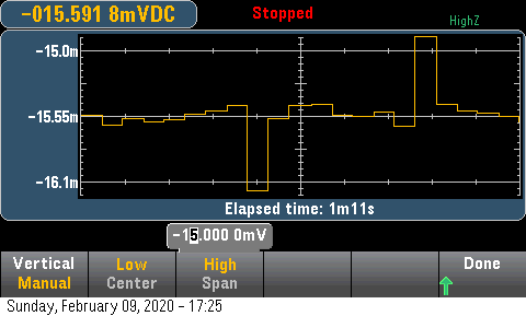
It’s not really bad — about -90dB — but I was expecting a better result. Maybe I had not calibrated the CMR and AC gain correctly. So I connected both inputs to a 30VDC supply and rotated the potentiometer to cancel the DC CMR error while looking at the outputs with a DVM. I got the DC CMRR to better than 100dB. Here’s a screen dump of the HP DVM showing the DC output voltage of the probe changing with the the applied 30VDC CM input. Each large spike is me turning off/on the 30V supply. The only thing that's important is the deviation between the large spikes. It’s 0.25mV! That’s more like what I was expecting.
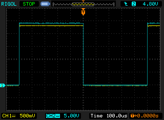
I set up a test circuit to provide a 1kHz 30Vp-p square wave (a more controlled waveform than the mains input) to test the CMRR. This was just a 2N7000 FET with a 3.3kΩ load resistor connected to a 30V supply, with the 2N7000 gate driven by the 3V scope calibration output waveform. Rise/fall times improved from ~1µs to ~100ns. I was able to calibrate out the DC and AC common-mode contributions to where the probe output looked like this to a 1kHz +30V CM square wave:

Ch2 shows the 30V square wave. I would call this less than ±1mV p-p variation. That’s > 83dB CMRR at 1kHz.
Unfortunately, I don’t have any appropriate equipment to thoroughly test the differential probe performance beyond this point, unless I get access to better lab equipment. I’ll have more/better data after the SMA connectors arrive and I can directly connect the probe to the scope input. But here's a scope trace that might anticipate the result:
Discussions
Become a Hackaday.io Member
Create an account to leave a comment. Already have an account? Log In.