 Bud Bennett
I can’t leave well enough alone. I still don’t have the SMA connectors to allow direct connection of the probe to the scope input, but I wanted to evaluate the probe in some more real world environments. I thought that a good test was to connect the diff probe to the gate drives of my T16 battery charger. These signals are 5-6V transitions with expected rise/fall times on the order of 10ns. In order to capture all of the information, you must have 35-70MHz of bandwidth. I have seen, and dealt with, quite a few buck converter gate drive issues over the years.
The top gate drive of the buck converter has a slower rise/fall time than the bottom gate drive. This is usually due to the top FET having a bit more total charge, Qt, because the top FET is a PCh FET vs. the NCh bottom FET. I connected the diff probe positive lead to the top gate signal and the negative lead to the GND of the battery charger. This is what was output from the diff probe:
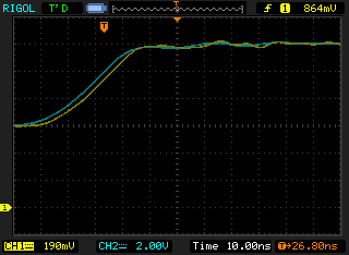
The yellow trace is the output of the diff probe, measured by CH1 of my scope. The blue trace is Ch2 of the scope measured with the 10x scope probe. This waveform doesn’t show much ringing associated with inductive parasitics. That could be because of the slower, 40ns, rise time or the care that I took with the PCB layout :).
I then connected the probe across the bottom gate signal. This signal is much faster, 5ns rise/fall, than the top gate.
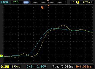
There is quite a bit of ringing. The ringing can be a result of many things: poor probe grounding, marginal stability of the diff probe amplifiers, unknown bad stuff? Usually, when confronted with unexpected circuit performance I tend to go back to the simulator and see if I can reproduce the effect and get a handled on the problem. I was looking for something that affected the second gain stage, or all gain stages, that would present as shown. I found two things: R23 & R24 had an effect on the ringing due to a fast rise/fall event, and the lead inductance that I was using should have caused ringing when the lead inductance interacted with the input capacitance of the attenuator. Or perhaps it was both, or something else?
In simulation, I found that the first stage amplifier ringing reduced when R23 & R24 were raised above 1kΩ. This damped oscillation was not present in the simulation until the stimulus had some common mode component. And this ringing was quite high in frequency and did not pass through to the probe output.
I also found that the longish leads that I was using to connect the diff prove to the Buck converter may be causing a problem. A 12 inch long 26 AWG wire has a self inductance of around 5µH. If you combine that inductance with the ~2.5pF input capacitance of the probe it will tend to ring at a frequency around 50MHz. If there is no resistance to dampen the Q of the input LC then the ring can be pronounced. A small amount of resistance in series with the probe inputs could remove most of the ringing at the input by reducing the Q of the LC circuit. If too much resistance is added to the diff probe inputs then the bandwidth would be compromised.
I added 470Ω to each of the diff probe's inputs, using leaded metal film resistors. I did not see a significant reduction in the ringing. So what's really happening?
I turns out that channel #1 of my Rigol 1102 appears to ring a lot more than channel #2. At this point I don't know which channel is bad, but my money is on channel #1. When I connected both channels of my Rigol scope to the diff probe output I obtained these results:

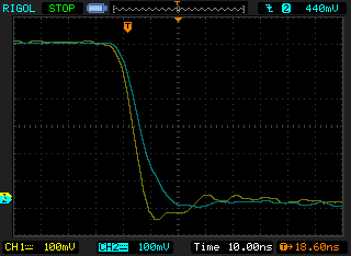
My Rigol scope has a problem with ringing on Channel #1. I think the diff probe performance is acceptable. [Caveat: I haven't directly connected the diff probe to the scope yet.]
Discussions
Become a Hackaday.io Member
Create an account to leave a comment. Already have an account? Log In.