 Matthew Reeves
In order to get a part to more easily come out of a mold it's important to add a draft angle to the walls. Straight parts drag against the walls as they're ejecting from the mold.
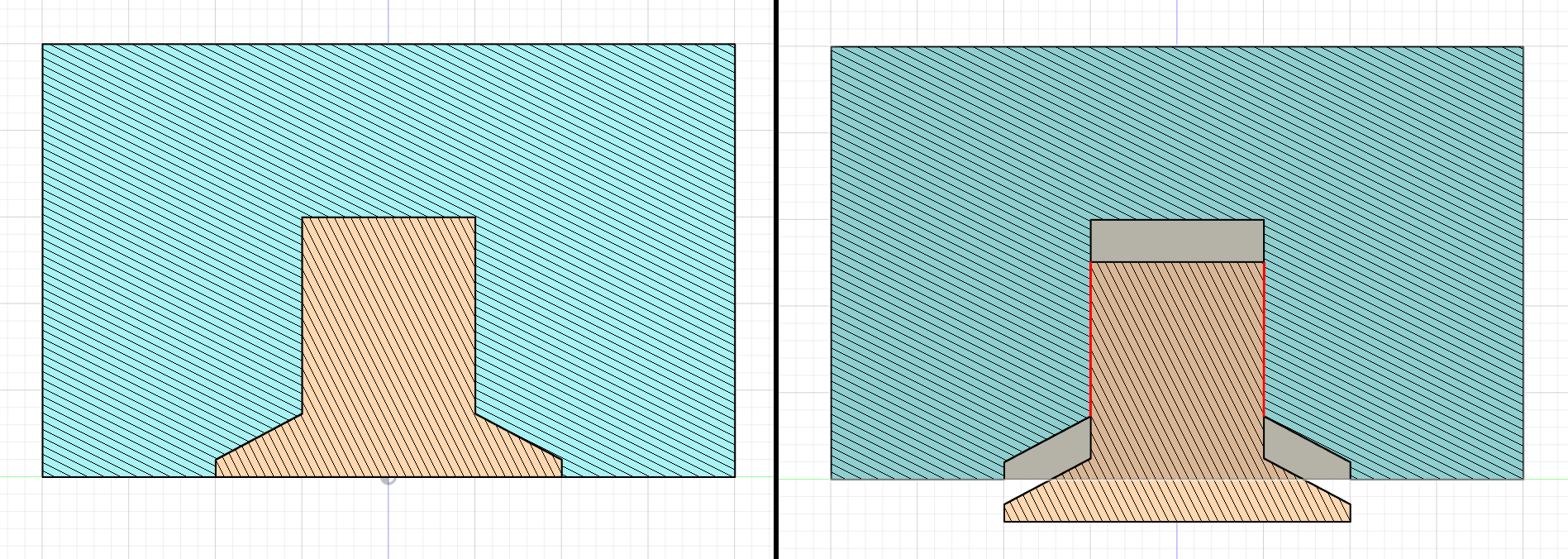
Whereas parts with a draft angle separate immediately.
Silicone molds are very forgiving when it comes to draft angles. The material is stretchy and you can get away with both vertical surfaces and even some undercuts on your parts. From what I've been reading, other molds are not so forgiving and adding draft angles is required. Even with the silicone molds adding draft angles is going to help the part come out of the mold.
It turns out Fusion360 has a tool to add draft angles to your models.
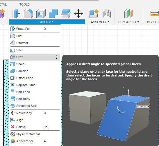
So far so good. Where I previously ran into trouble was that adding a draft angle to the DIN rail clip made the magazine grip the rail badly. The draft tool is supposed to allow for deselecting certain faces but I found that interface to be too quirky to work with on my model and I added draft angles during the extrusion steps.
I'm about to revise my design based on what I learned from a test casting, so I thought I'd try out a few ideas on how to work around the issues I hit with the Draft tool.
I'm making changes to fix a few specific problems.
I wasn't very careful when pouring my test mold and I wound up with some problems with some tall narrow areas. For the main tape passage I'm just going to have to be careful not to trap an air bubble, but some of the other small openings don't have to be designed this way.
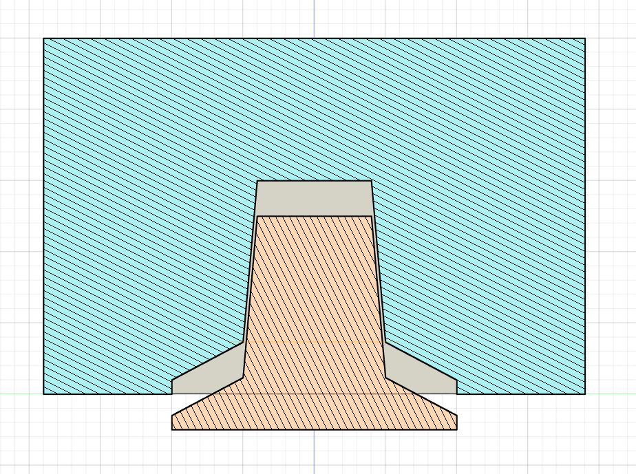
Also, I'm missing the flat front and larger top nubbin from the original design as that gave additional room for labeling.
So, getting started!
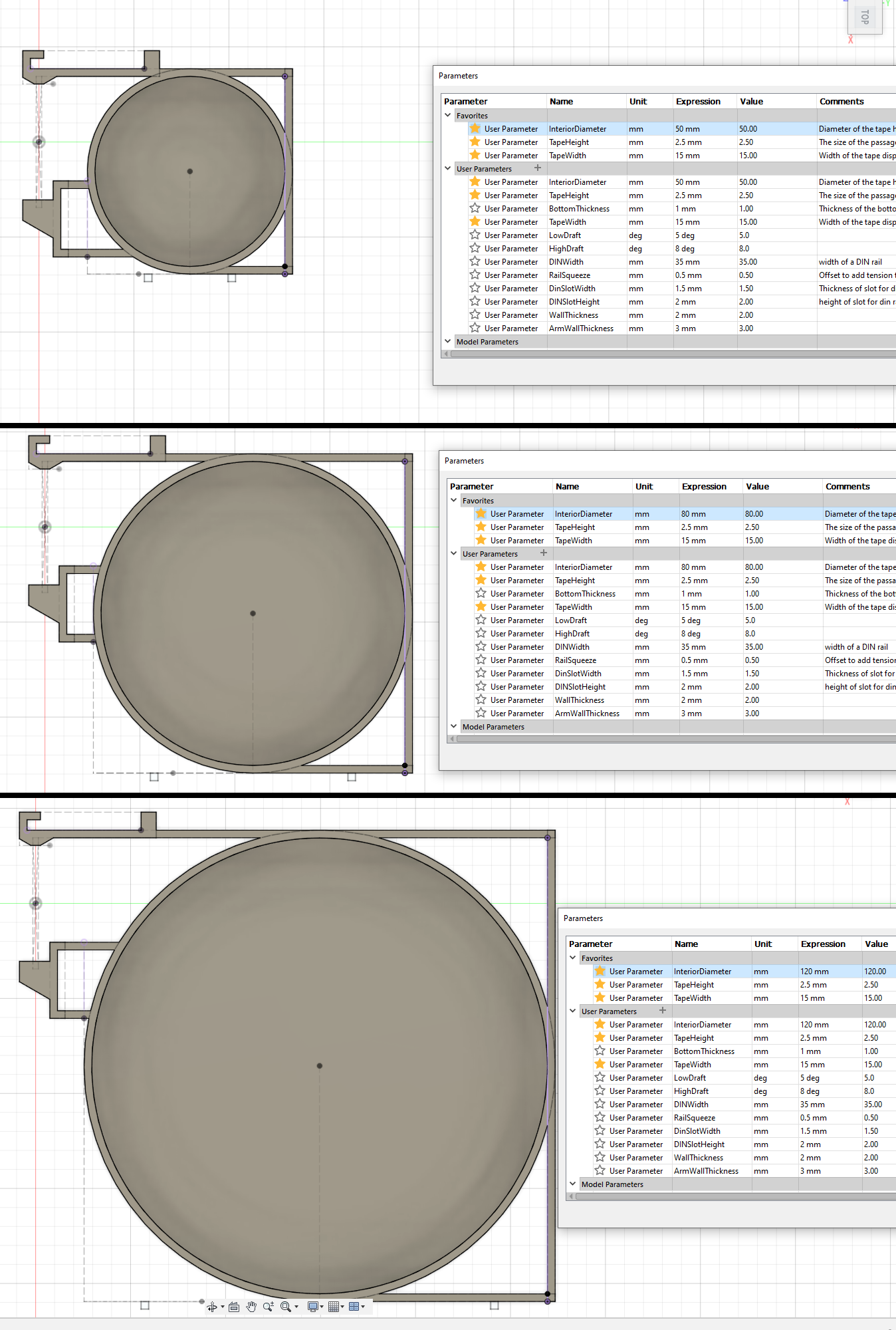
First thing I'm doing is adding a bunch of parameters. InteriorDiameter, TapeWidth, and TapeHeight reflect the tape dimensions and will be adjusted to produce multiple outputs.
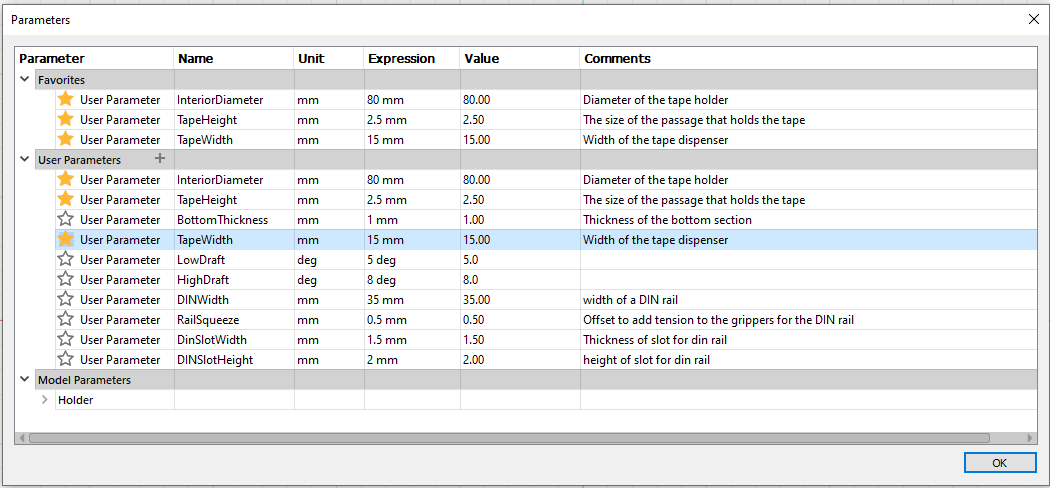
Some of the other parameters (RailSqueeze, DINSlotWidth/Height) relate to fitting printed parts together and I prefer adjusting them in the parameters dialog. DINWidth is there as a constant so I can type DINWidth-RailSqueeze as a dimension.
LowDraft and HighDraft are values that are going to be used to set draft angles. 5 and 8 are absurdly high angles, but it makes it easy to see when I've flipped angles backwards. I'll change those to something more like 1.5 and 3 degrees for the final product.
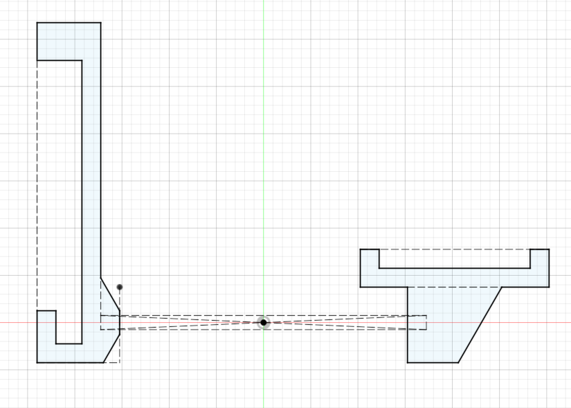
I'm going to create the drawing for the DIN rail connector except that i'm going to leave out the actual critical surface for the rail connection. If I wait until the last step then I can have a lot more control over what (if any) draft angles are used.
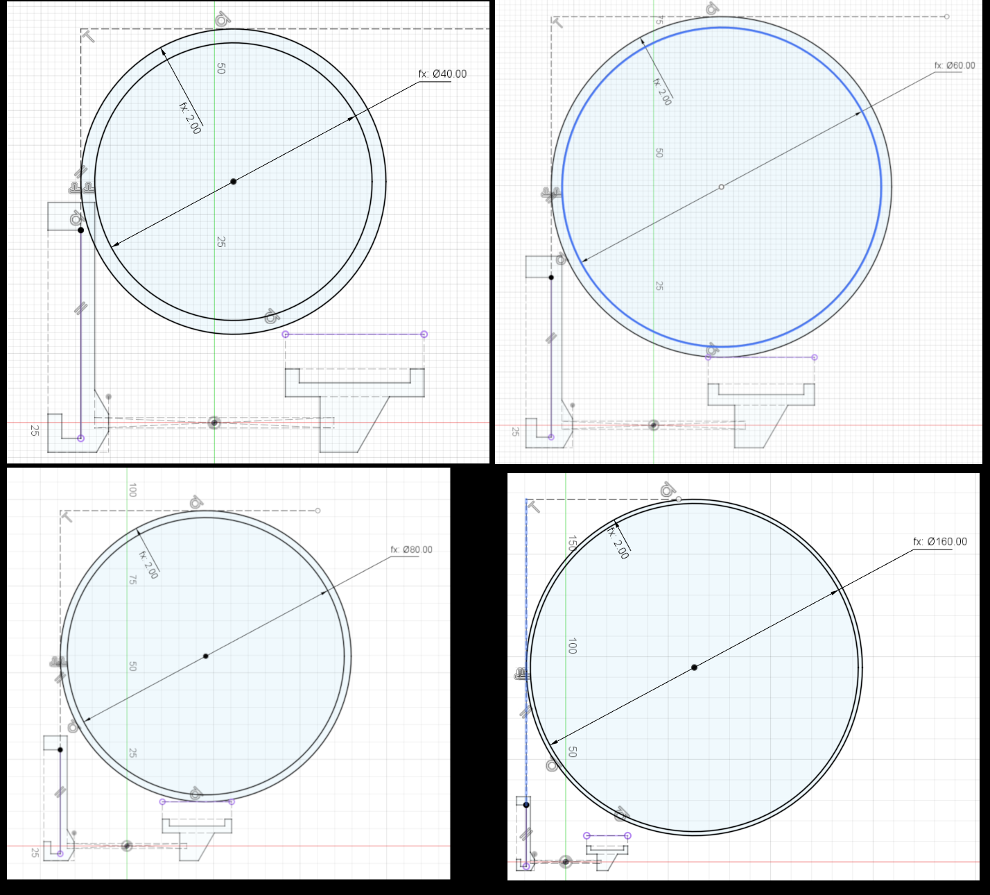
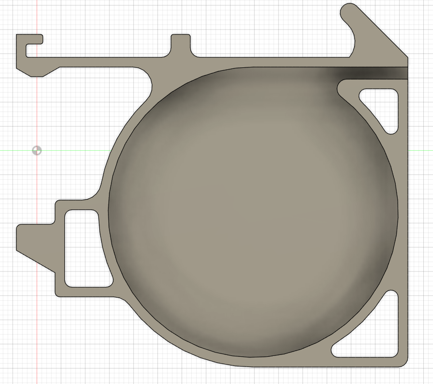
The next bit is the big circle that holds the tape. The exterior of the circle is constrained to be tangent to the DIN rail. This leaves the circle unconstrained in one axis (up/down in the picture).
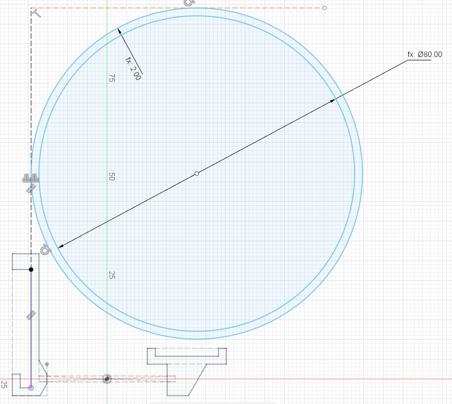
To constrain the second axis I construct a horizontal line that's offset from the other part of the DIN connector and make the circle tangent to that line. I've found this to be a very reliable method of constraining parametric geometry and Fusion360 won't randomly reverse dimensions or flip them around to odd angles.
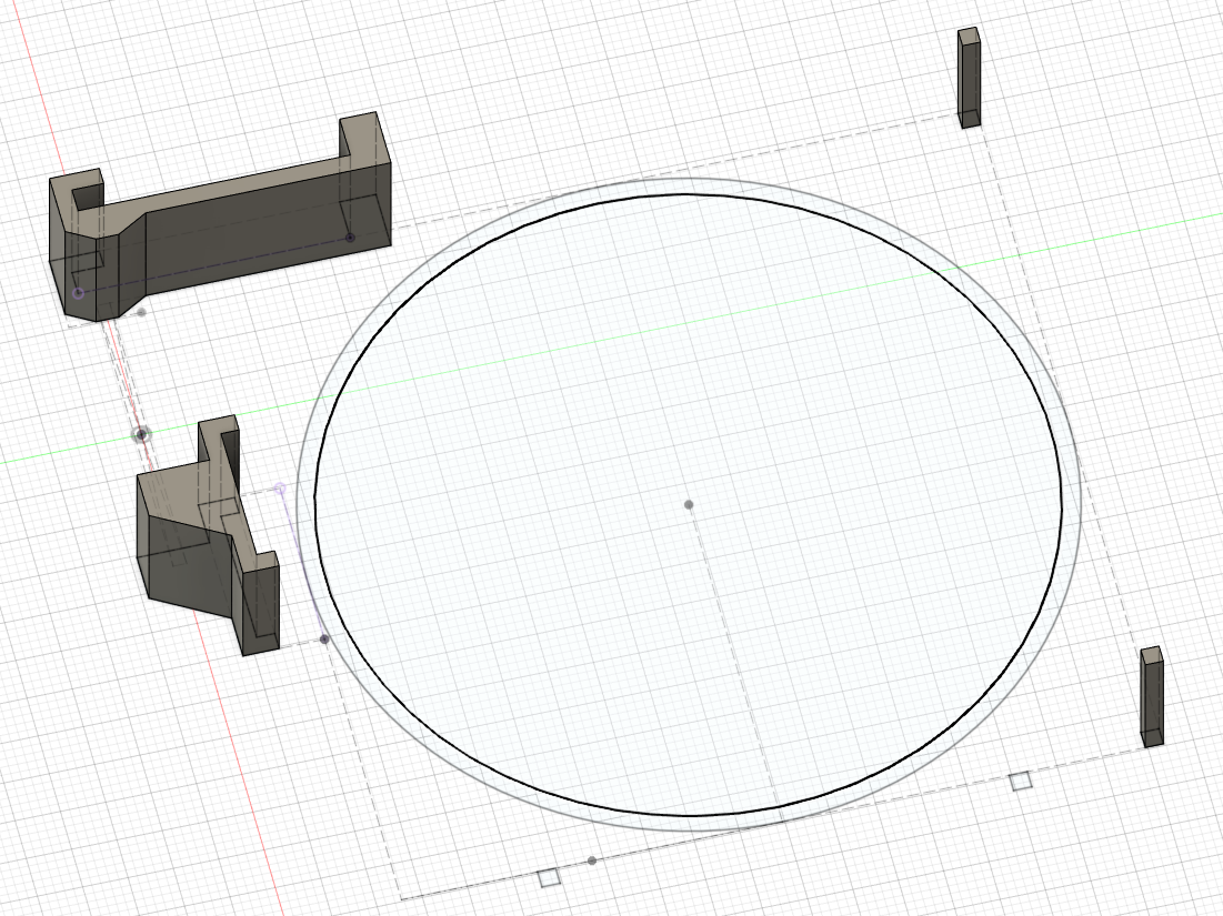
Then it's a quick job to build some squares in the corners of the design and extrude once with the floor thickness + tape thickness.
From now on try to only use extrude with distance of To Object. Connect things together.
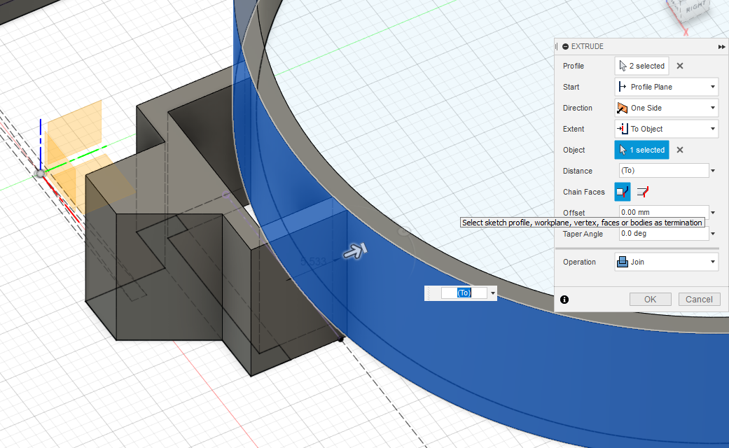
That seems to keep Fusion360 from getting confused when the parameters change. That becomes doubly important later if fillets are added and Fusion tries to figure out how to maintain the features.
Now check to make sure the model is stable over a reasonable span (in this case 50mm to 120mm).
Keep going but:
* Don't apply a fillet between the interior and exterior of the geometry
* Don't add the passage for the film
Now apply the draft tool. The hard corner between the interior and exterior makes fusion360 do the right thing
Make sure to get all the angles flipped around the right way.
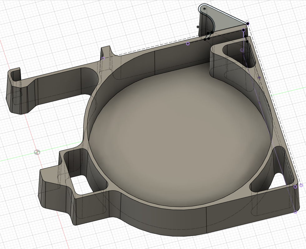
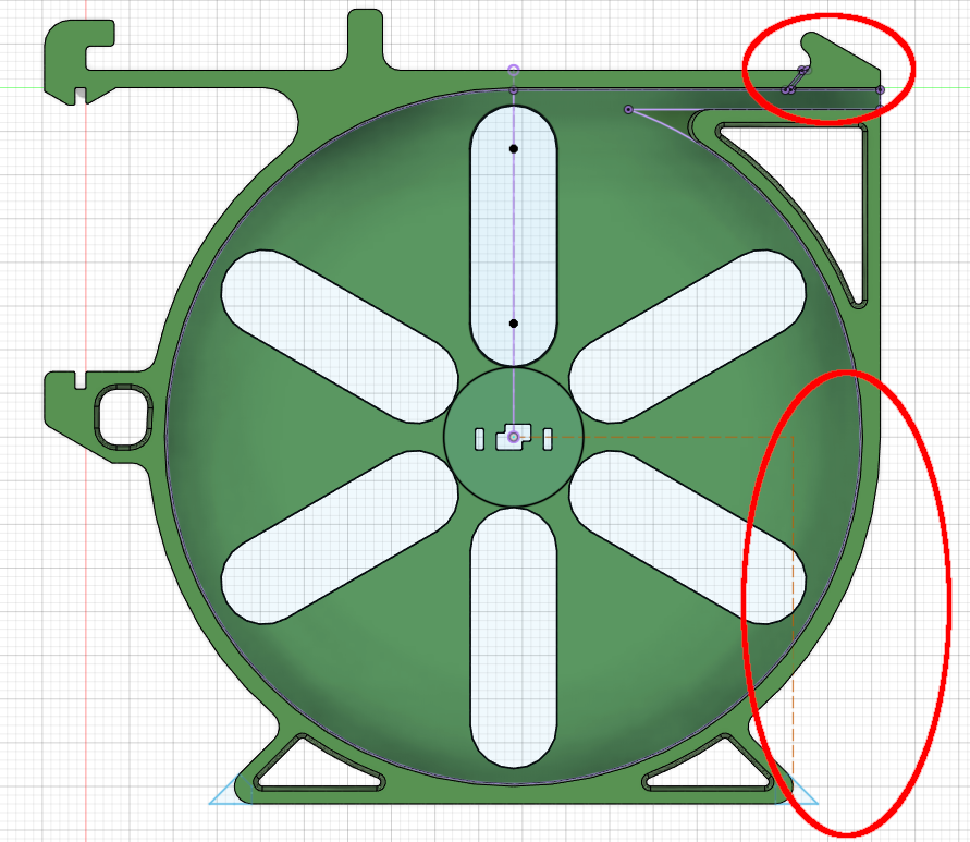
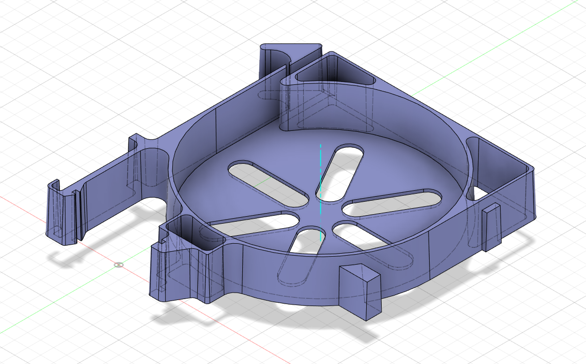
Now cut the critical surfaces and add some non-angled feet so it can stand upright. Also I thickened up the compliant arm at the top.
Actually, now that I understand the draft tool a little better I think that I could've gotten the same result by being careful about what what surfaces maintained a tangent curve and which ones stayed at rigid angles.
And now testing to make sure the parametric modeling still works:
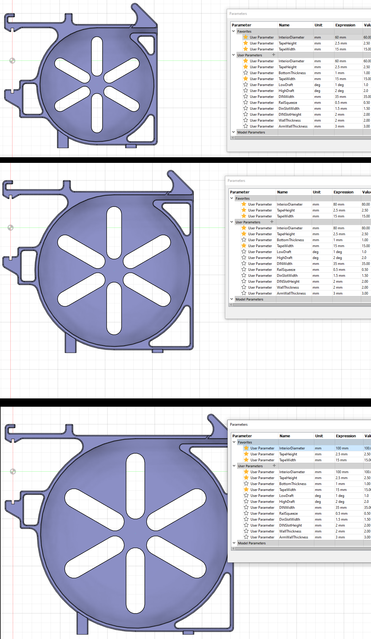
Everything works! Well... mostly.
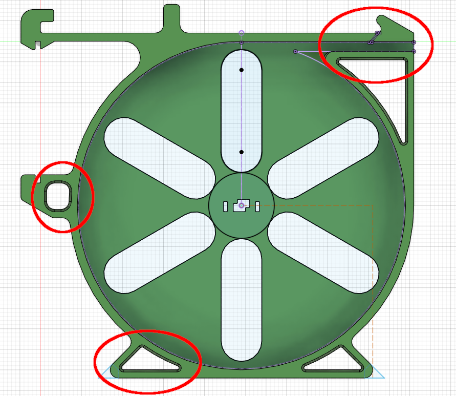
Dropping the radius below 50mm is starting to break features. That's ok because I have no need for parts of that dimension. More importantly, there seems to be enough complexity here that Fusion360 starts to get quirky as you change the parameters around. It usually works, but I find that I need to periodically hit the undo button especially if I've been repeatedly changing the parameters without closing the parameters dialog.
Next is some test prints. And possibly changing the cutout pattern because I've realized it looks a lot like the walmart logo.
Also, I need to figure out what sort of license I can release things under so that I can post .f3d files to github (probably BSD or some creative commons type thing)
Discussions
Become a Hackaday.io Member
Create an account to leave a comment. Already have an account? Log In.