Dominik Meffert
-
Wire Feeder Upgrade
03/21/2020 at 22:52 • 3 commentsMaybe I found the cause of all the problems:
I just realised that the wire is randomly slipping in the wire feeder, so that the amount of "extruded material" was wrong the whole time and this could have caused all the problems I had with printing.
That could mean there were no problems with heat, settings, material, (oxidation), just random amount of "extruded material". What a shame that I didn't noticed that earlier.
Will change the design of the wire feeder for reliable operation.
![]()
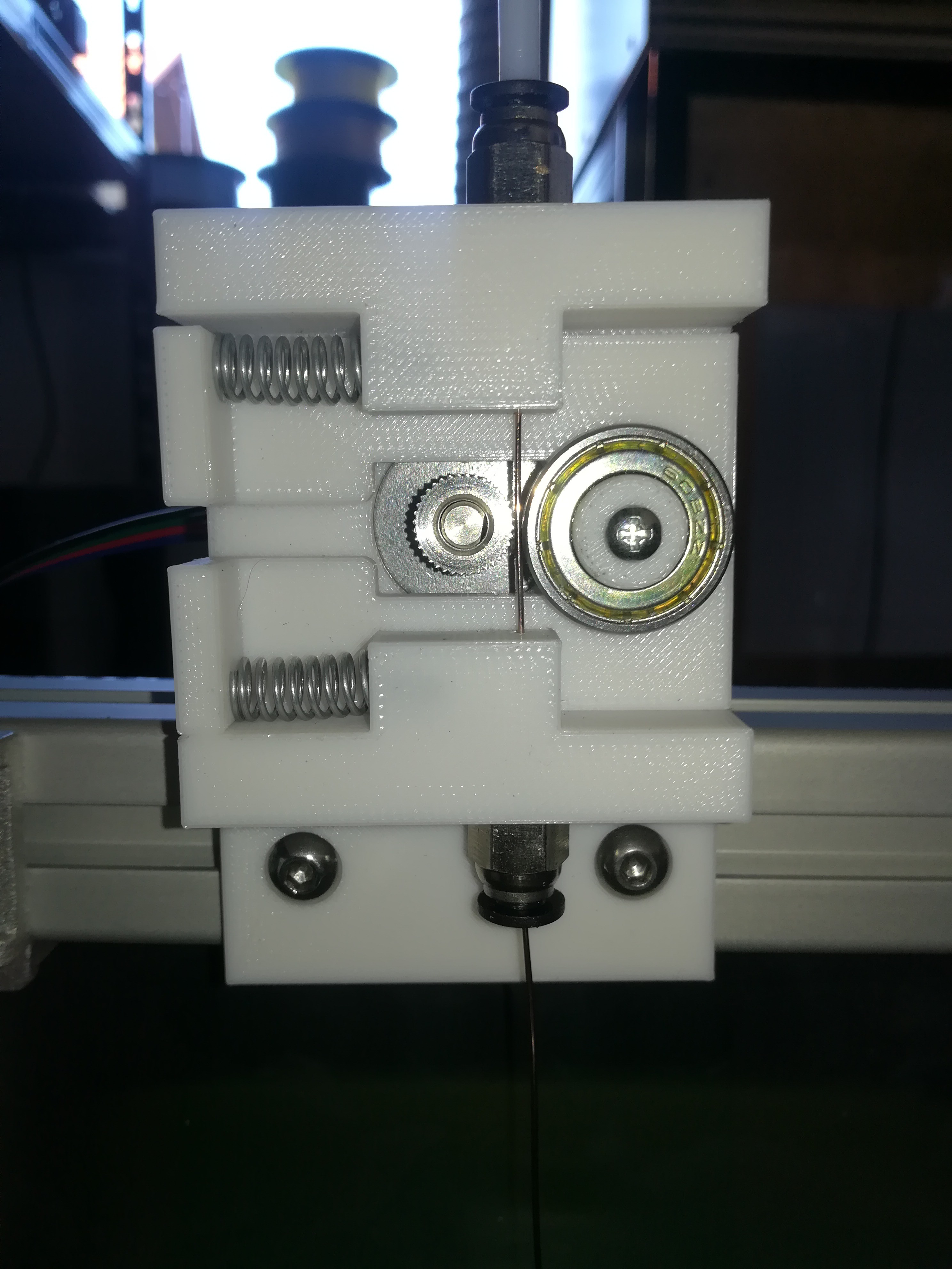
I designed a new wire feeder, but unfortunately it worked as bad as the last one.
I also ordered a wire feeder roller for building a wire feeder that hopefully works. It will be delivered later this week.
![]()
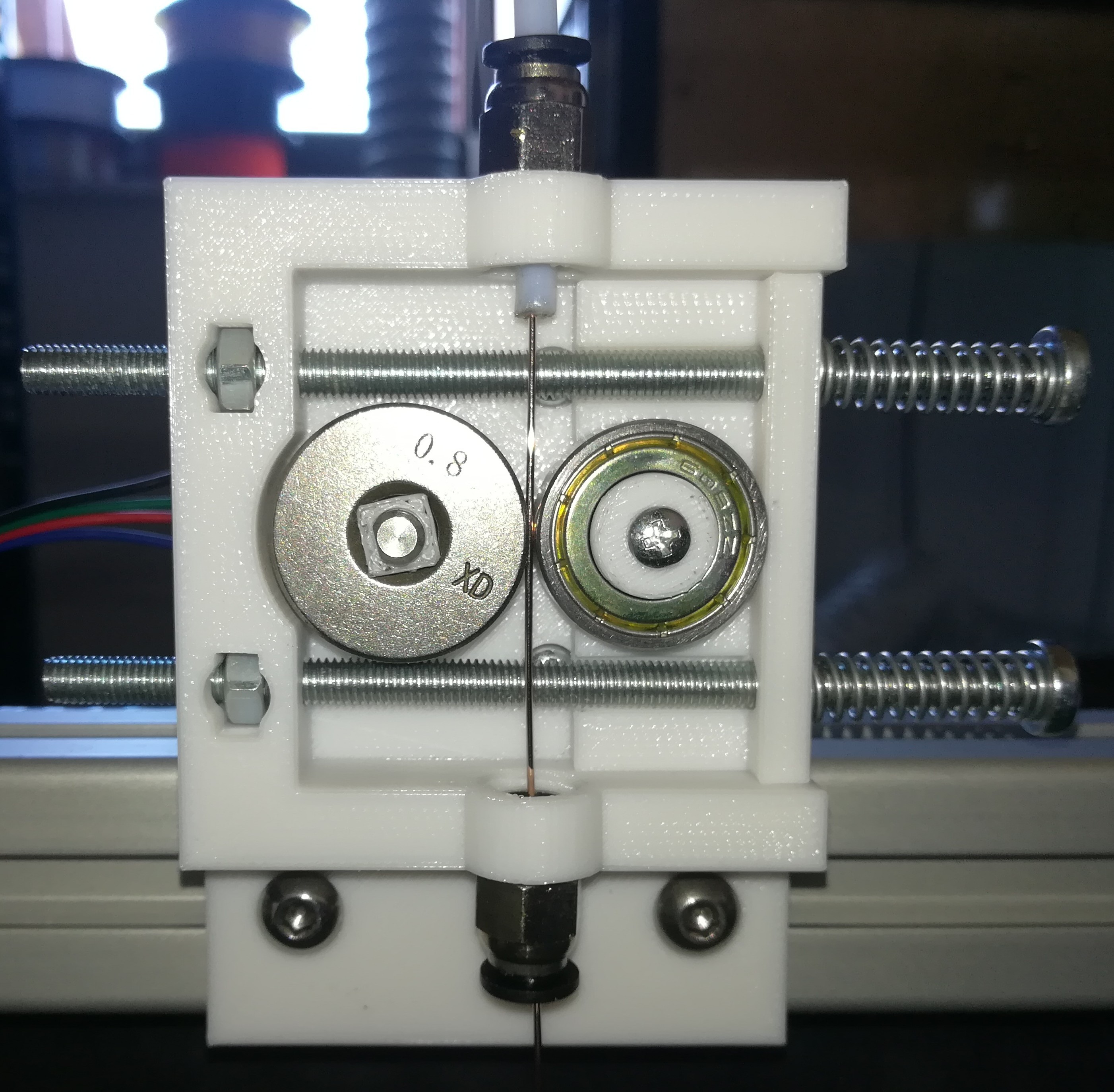
Here is the new feeder with the wire feeder roller and it works very well. The feedrate should now be as set in the slicer software.
-
Testing with Shielding Gas
03/21/2020 at 22:25 • 2 comments![]()
I tried out spraying CO2 and Argon Gas on the melted metal while printing, but unfortunately I couldn't see any difference in print quality. Maybe I did something wrong or it has something to do with using resistance welding instead of arc welding. Will maybe test it again in the future...
-
The Problem is Oxidation/Contamination
03/20/2020 at 18:15 • 0 commentsJust tested printing with flux core wire and the first layer printed very well, but as soon as the second layer started the melting stopped completely - I think it lost its conductivity due to a layer of less conductive material covering the metal. With the steel wire the socond layer melted, but the melted material did not fused together...
I also tested aluminum wire. It fused together but was very brittle.
Will test thicker steel wire, maybe it helps when there is more melted material at once.
-
Plan B: Automatic Spot Welder
03/20/2020 at 06:47 • 2 commentsSo for the case that I can't get it to work, here is another usecase for the machine, to be not completly wasted effort - Automatic Spot Welding.
The machine could be used as automatic spot welder, so that you can set the parameters like power, duration, number of pulses and pressure in the GCODE.
For that I could add another welding tip in the middle of the builtplate for using it as lower electrode.
You have then just to put your two workpieces between the two electrodes and start the right file from an SD card.
After a short countdown the workpieces will be clamped between the electrodes and will be welded together with the selected settings.
The clamping pressure can be set with the Z axis parameter which moves the spring loaded buildplate more or less close to the printhead.
-
New Parts and more Testing
03/18/2020 at 20:45 • 0 comments![]()
![]()
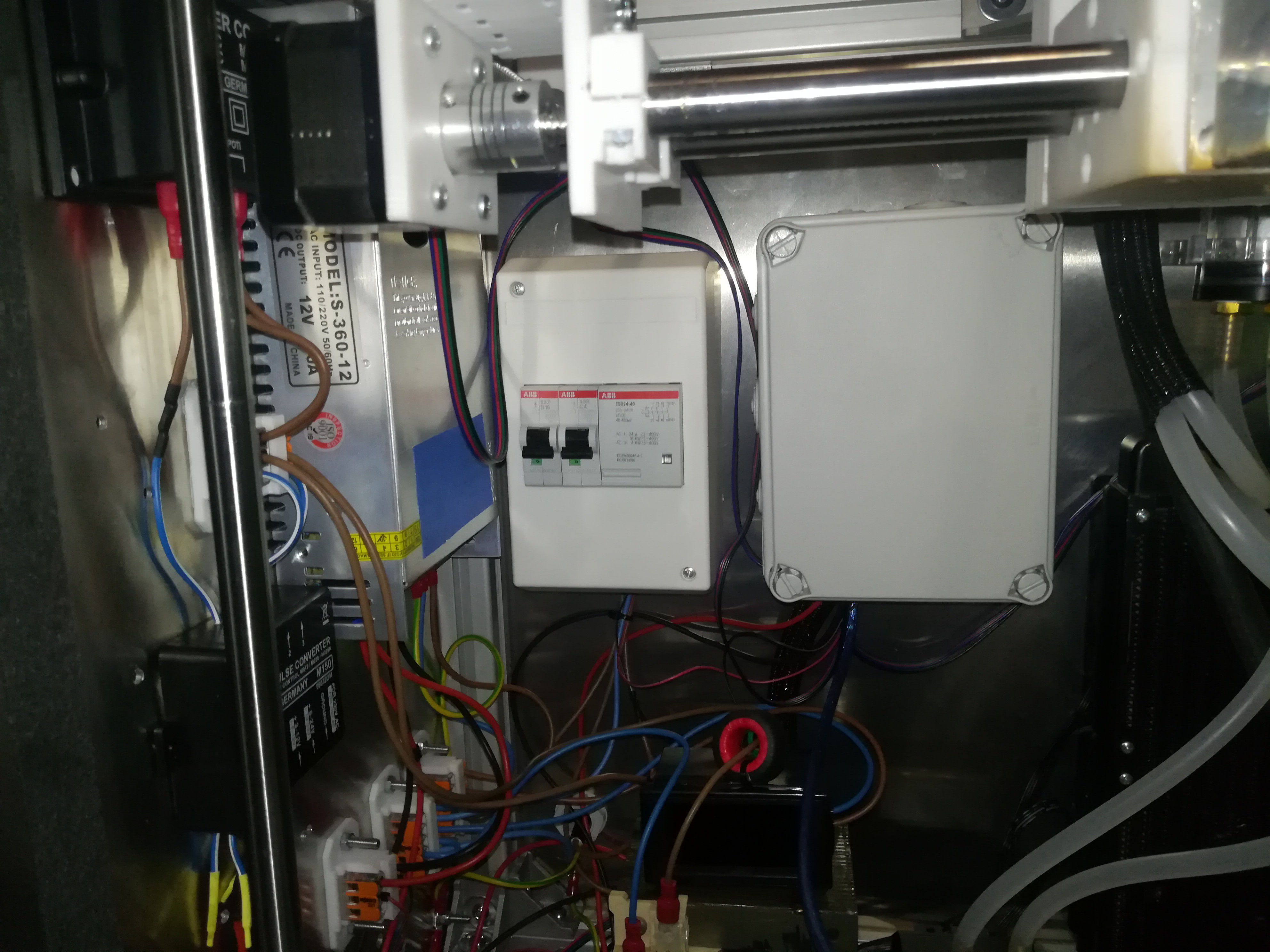
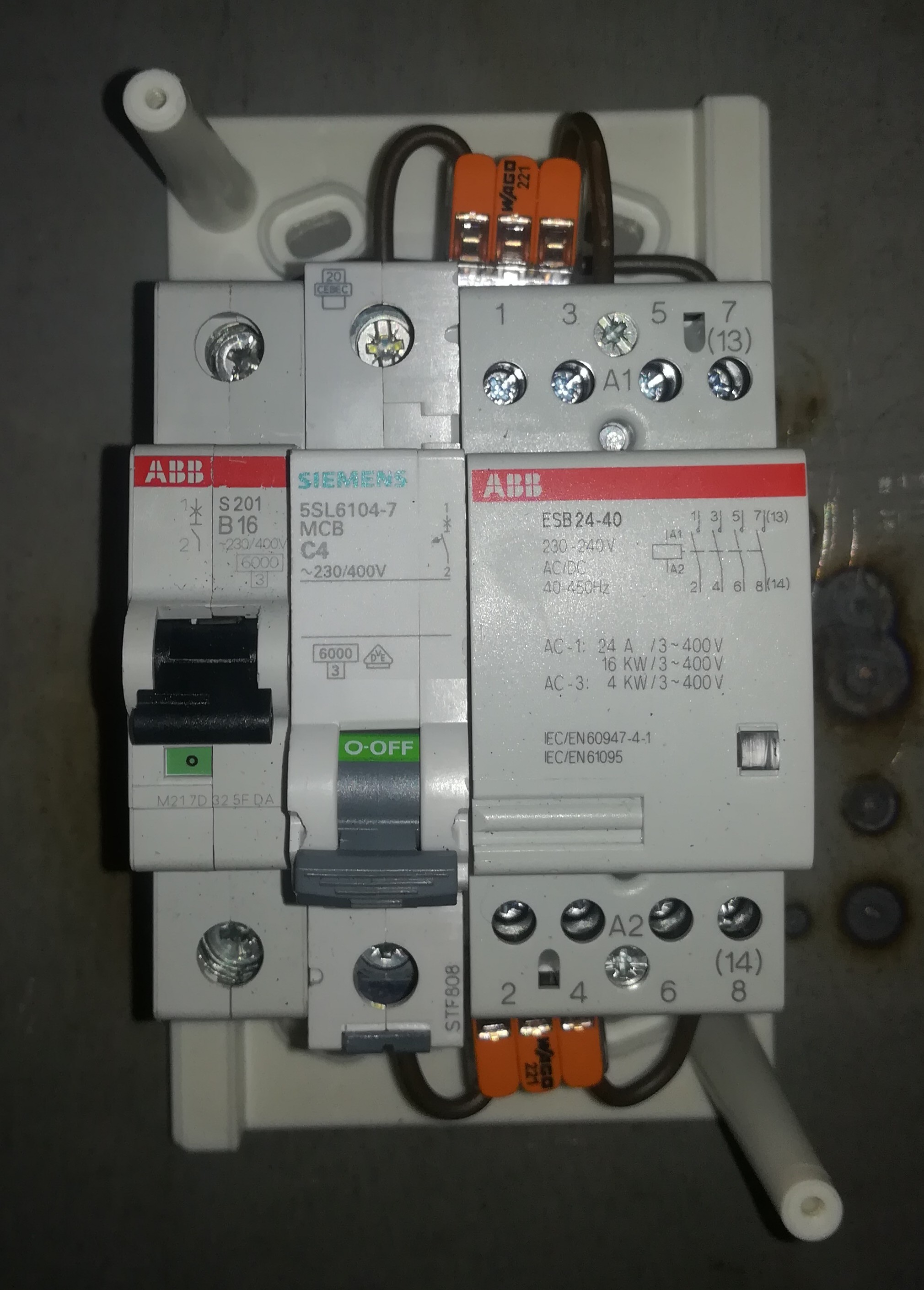
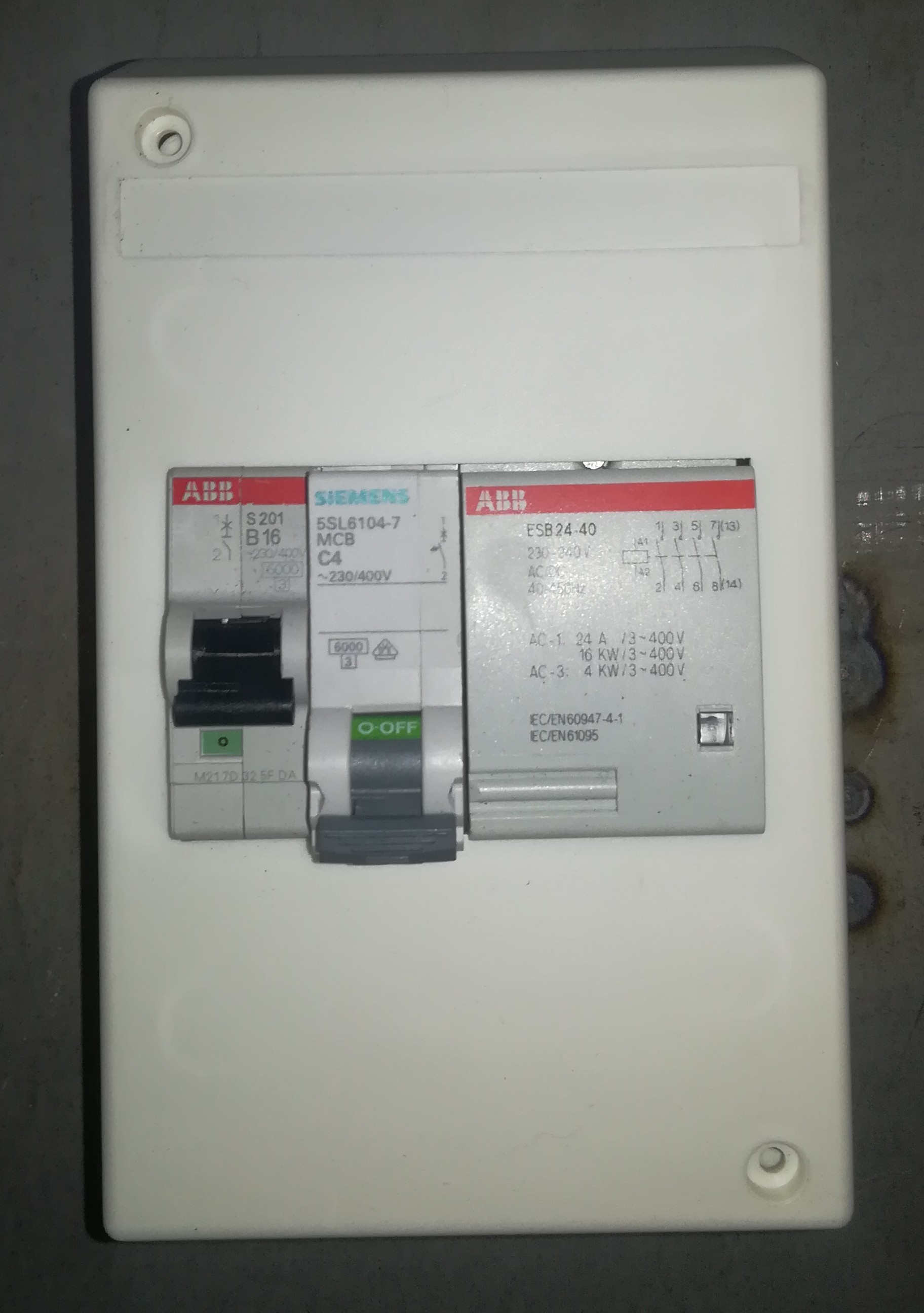
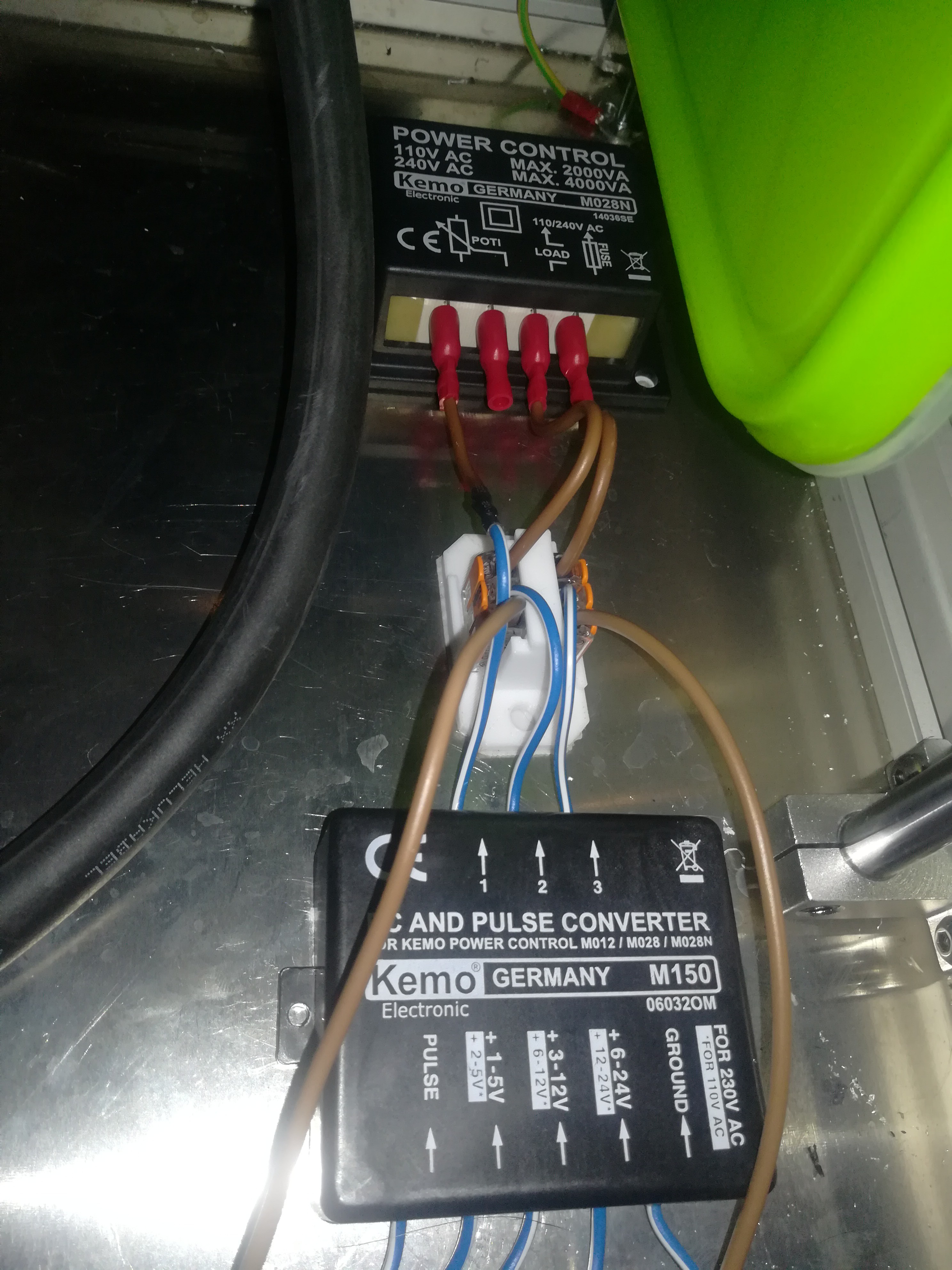
The resistor plate got removed and a small fuse box was placed on its location, containing a 16A breaker for the whole printer, a 4A breaker for the work current and a contactor for triggering the filament runout function if the 4A breaker trips. The ramps board got also placed in a box to protect it from sparks and the phase-fired controller and pwm module got moved on its old location.
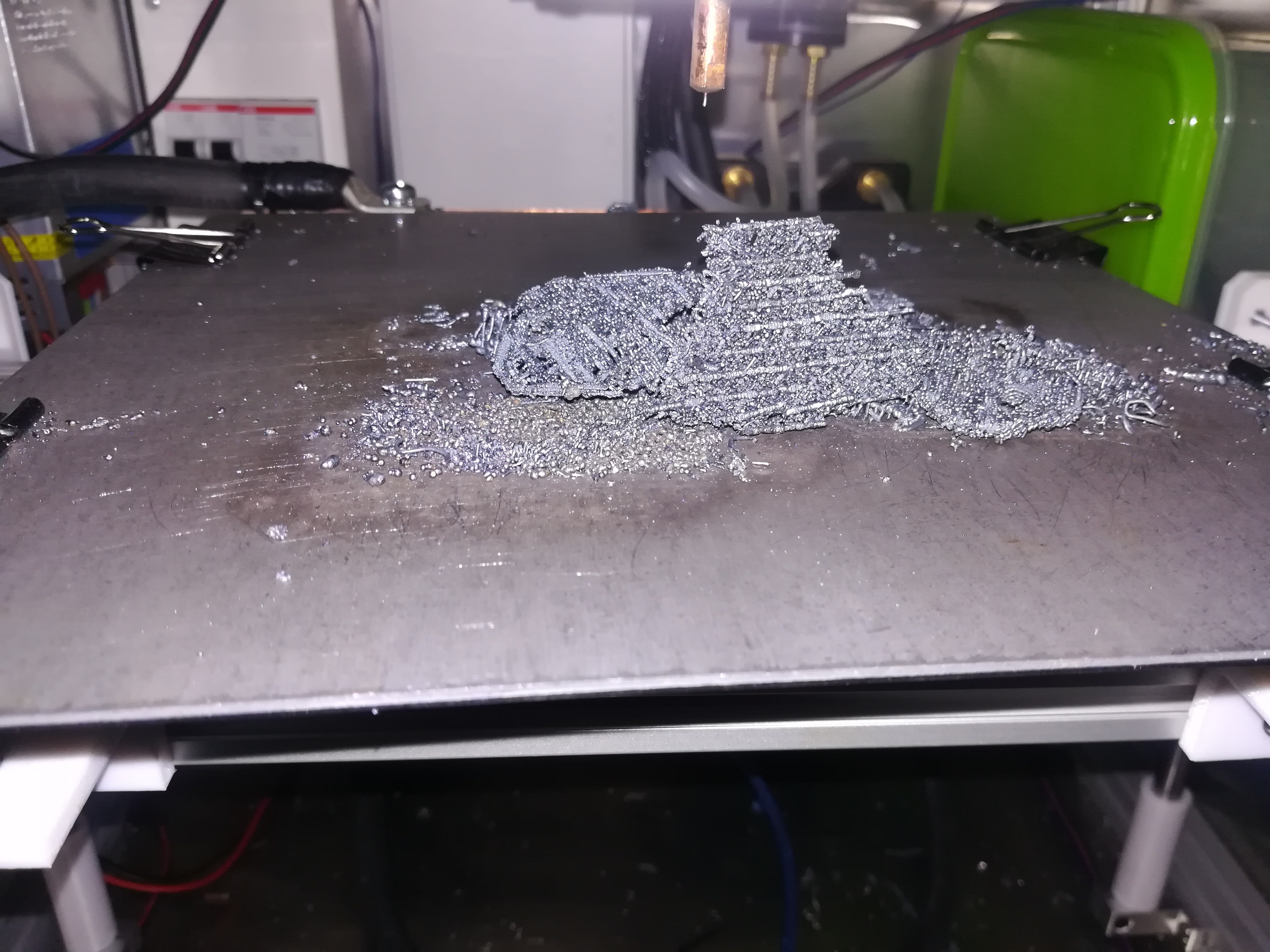
I did also some (unsuccessful) testing
![]()
![]()
![]()
![]()
I tested with different intensity, extrusion multiplier, layer hight and printing speed, but no success.
Maybe it could be a problem with oxidation what prevent the layers from fusing together.
Ordered 0.9mm flux core wire for more testing.
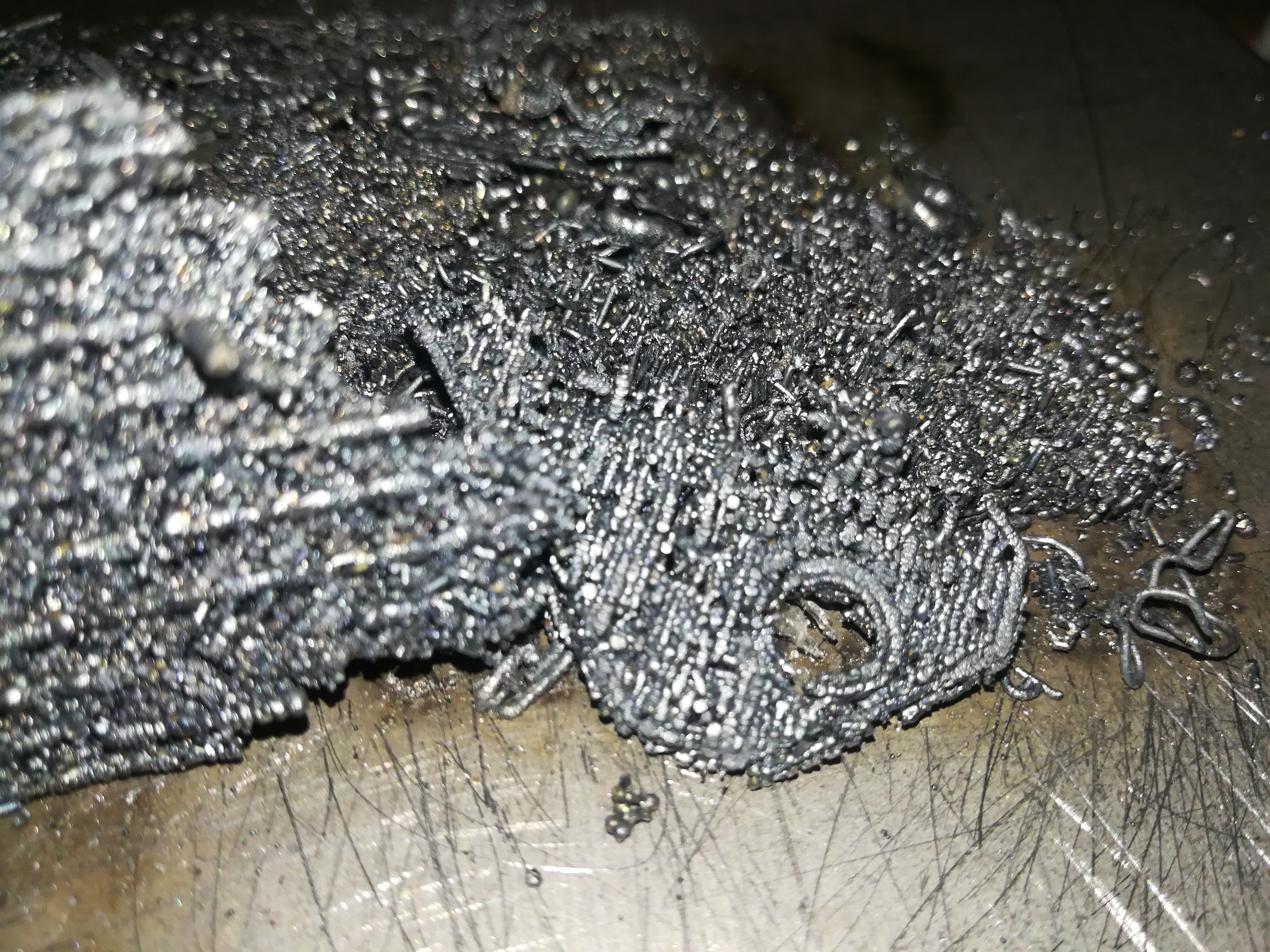
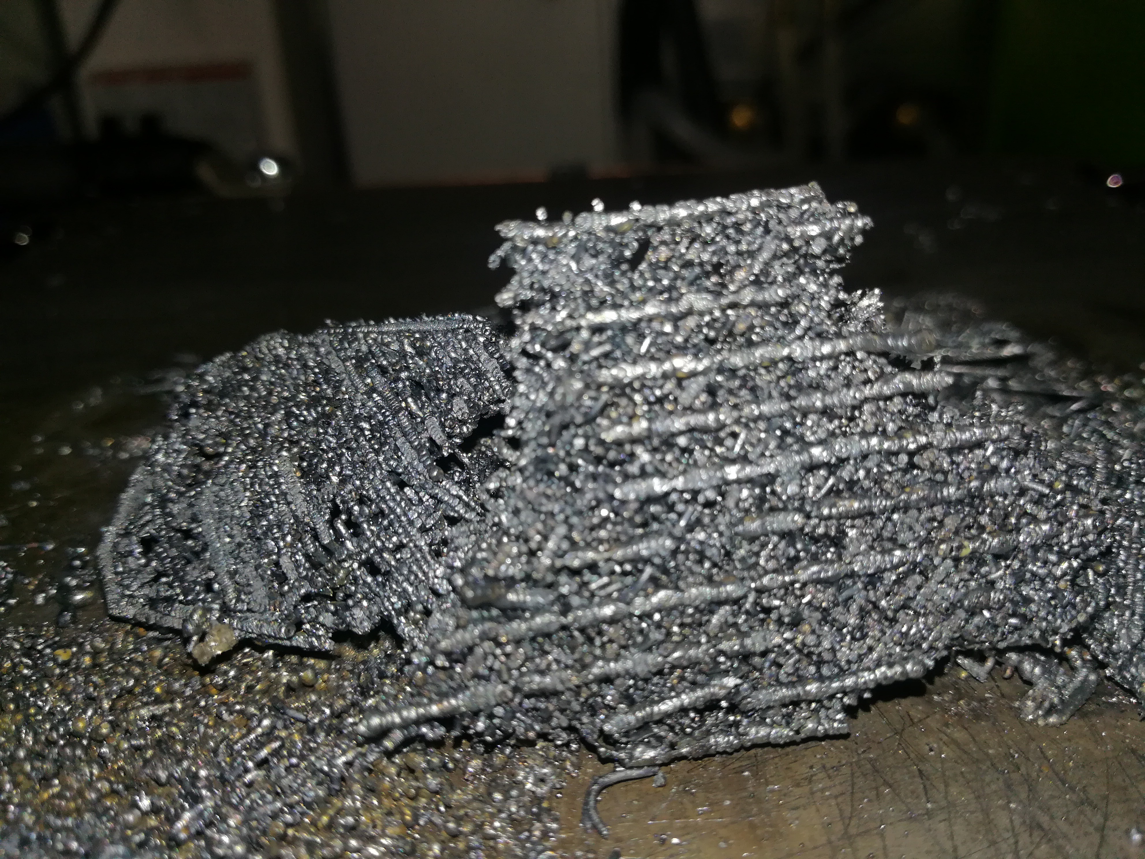
Update:
I tested it again with a 0.9mm nozzle and 0.6mm wire and it seems like the larger nozzle is an improvement. With the 0.6mm nozzle the wire got stuck in the nozzle when the heat reached the nozzle, but with the 0.9mm nozzle there is enough space to prevent that.
I still think oxidation is the problem because the "printed object" consist of many small brittle pieces of wire which are not fused together. Sometimes it seems like the melting stops because the wire lost its conductivity which could be a sign of an oxid layer covering the wire. After scratching over the buildplate or printed object the melting starts again.
-
More Power without Resistors
03/13/2020 at 06:41 • 2 commentsI want to test printing with more heat and now where I have the phase-fired intensity controller I can test removing the resistor plate and replacing it with a circuit breaker and a contactor, which should trigger the filament runout function if the breaker trips.
If that happens, you would be able to fix what caused the tripping and continue printing after that. The rating of the circuit breaker would depend on the current the 50mm² cable and transformer can handle without getting too warm. Getting rid of the resistor plate would also reduce cost and simplify the build of the printer.
I tested it out and yes, I would say it is helpful for improving print quality. With more power the printed part fuses better together and I noticed some Interesting behavior.
I tested shorting the work current by driving the nozzle on the buildplate to see whether the breaker trips, but with a 10A breaker the copper nozzle melted a bit when I tried to increase the intensity to max level. So the circuit lost contact everytime befor the 10A breaker could trip. Will continue testing with a 6A breaker. With higher power while printing there is also more arcing.
I noticed that like on FDM printing the junction in the layer itself was stronger than the junction between the layers.
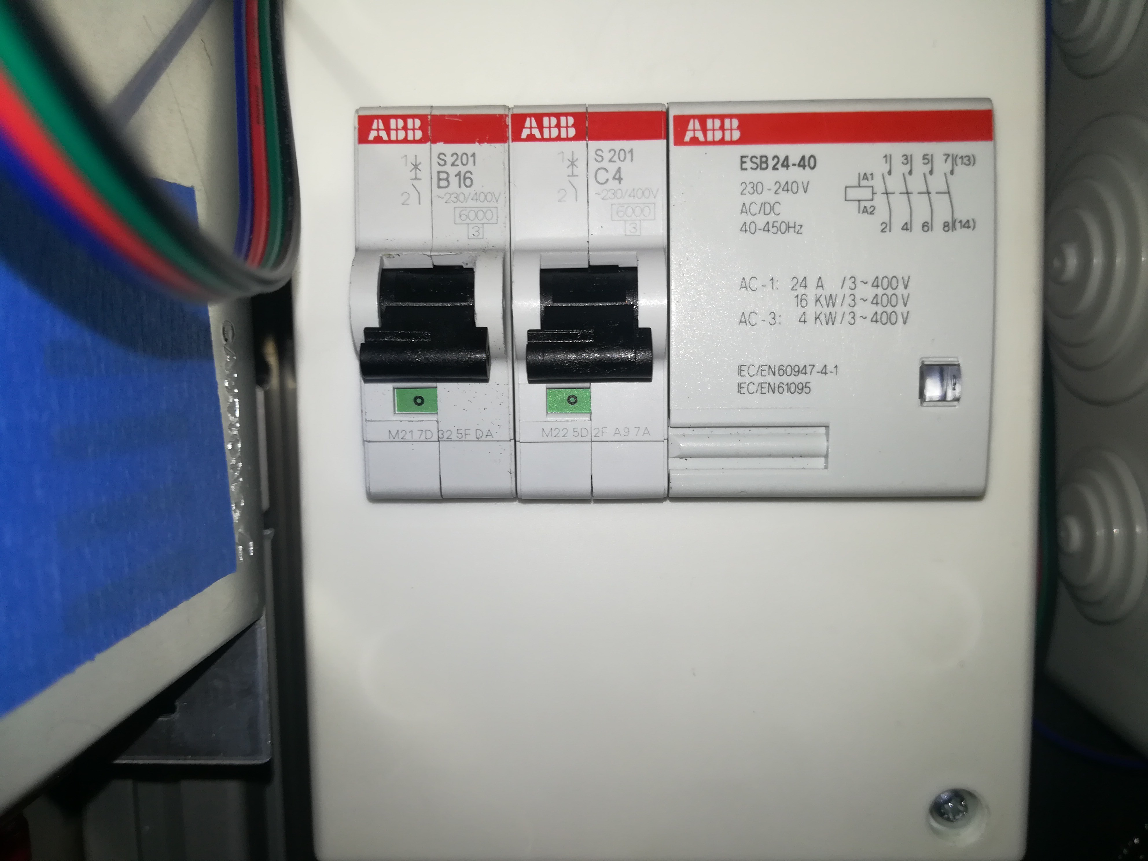
Added a C4 circuit breaker for protection. The breaker trips before anything overheats, so it should be a good choice.
![]()
![]()
B16 for the whole printer
C4 for the work current
Contactor for triggering filament runout function if the breaker trips.
(Just ordered one from ABB for more uniform looking)
-
Heatbed
03/12/2020 at 22:54 • 2 commentsI added a heated bed to the printer to reduce the temperature loss through the buildplate, which could maybe help with adhesion and reduce warping of the steel surface underneat the printed object.
Wheater it helps or not is pure speculation, but some people told me it would help and I thought so, too. And so I tested two different heating designs.
![]()
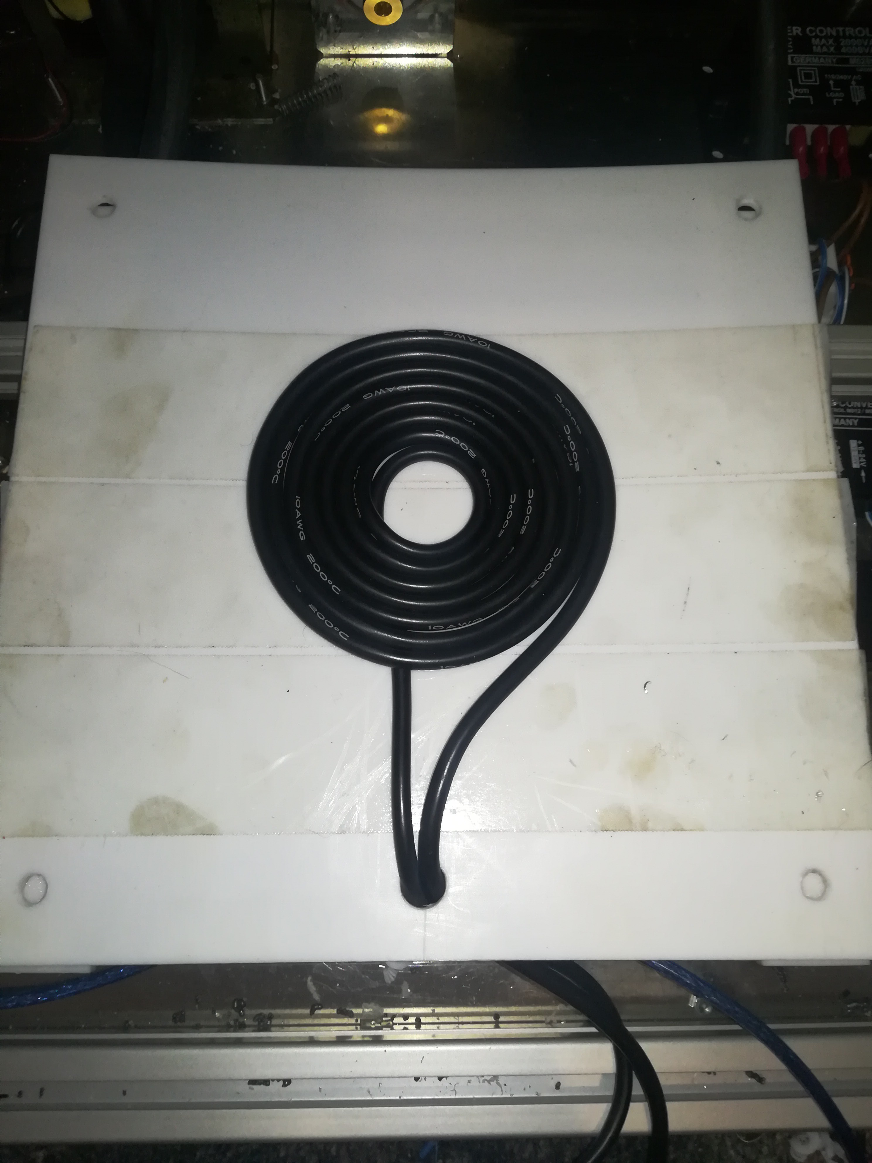
First I tested an induction heating design for reaching the highest possible temperature without radiating heat to the rest of the printer. The design consists of a power supply, a ZVS driver and the induction coil.
The induction coil is made of a AWG 10 silicone cable which is rated up to 200°C which lays on a PTFE plate which is rated up to 260°C. The coil is coverd with stovepipe access door sealing which is rated up to 1100°C to prevent the cable from touching the buildplate.
Unfortunately there are some problems, which maybe make the design a bad candidate for buildplate heating, until I can find a solution to them.
First I tested it with 12V, which draws 340W max, which heated the plate to around 100°C. I measured the themperature with an IR thermometer, but got no usable reading. It indicated room temperature, even though I could boil water (Still don't know why I got this false reading). So I used a barbecue thermometer.
Next I tested with 24V and this is where the problems started. With 24V and the buildplate direct above the coil it draws more than 800W, what shuts down my 600W power supply, from which I thought it could deliver more than enough power....
So I tested elevating the buildplate some millimeters above the coil, until it only draws around 500W - what worked.
With 500W the plate reached above 250°C, which was the highest value the barbecue thermometer could read and after some time the carbon steel plate changed its color above the coil and begun to bend. The PTFE plate underneat the coil started bending, too. So I stopped testing and measured the temperature of the coil which was around 190°C - very close to the limit.
I think for now these are not the right conditions for safe and reliable operation and so I tried a second approach.
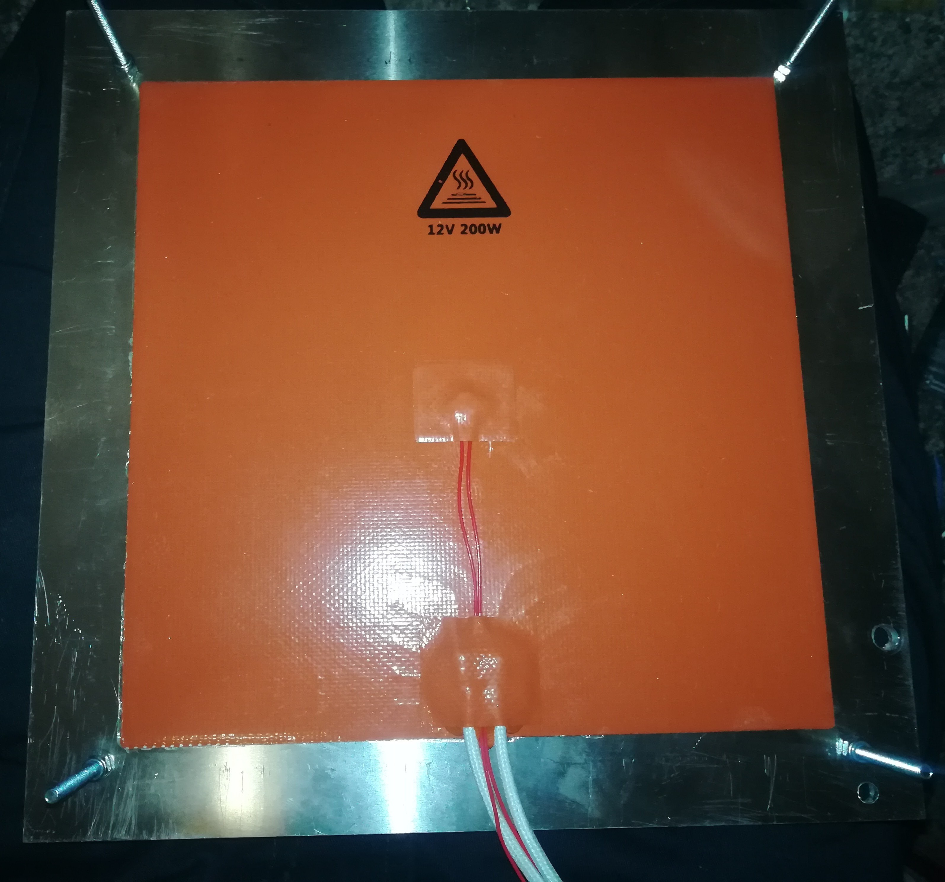
![]()
It's a 12V 200W silicone heat pad which is rated up to 190°C, but the 468MP double sided tape at its back is ony rated up to 150°C, so that is the limit for it until I use silicone glue or something with a higher temperature rating.
I tested it for a short time and it reached 80°C on the buildplate with 100°C on the heater. I think if I had waited longer, it would have reached 100-120°C or more on the buildplate. Next time I will test it for longer.
So the bed is now heated - Maybe the print can benefit from it, maybe not, I will see with further testing.
Update:
I figured out that the problem with the object not sticking to the buildplate was caused by bad first layer quality and heating until the part unwelds itself from the buildplate when the head crashes into the part. So it seems likely heating the buildplate is unnecessary and I will maybe end up not using it at all.
A small setback that heating the buildplate has turned out as not worth it, but at least I tested it out...
-
Controlling Heating Intensity
03/08/2020 at 00:01 • 0 commentsI added a phase-fired controller to be able to control the heating intensity in the slicer settings. It's wired to the D9 output of the RAMPS board and controlled by the part cooling fan parameter.
Unfortunately it turned out like the one I bought works only in a range from 0-80% if controlled via pwm or 3-12V, but I think it should be still enough - I tested it and it still worked.
Actually the metal melting system / hotend draws not very much power, just a few hundred watts depending on the resistance of the working circuit.
![]()
-
Another Test
03/03/2020 at 08:18 • 16 commentsAnother test with different settings.
In the video you can see the wire melting just like plastic filament. That's how it should look like. In contrast to arc welding there should actually be (almost) no sparks at all.
The problems remaining are problems with the first layer and that the printed lines are not lying even next to each other. Maybe I could solve this by adjusting the first layer settings and by reducing rhe space between the printed part and the nozzle. I think it could be possible to leave no space between them as long as there is melted material underneat it, which stays melted until the nozzle is serveral millimeters away from it. The extrusion rate is also not perfect at the moment.
In the next few days I will test some new hardware...
-
First Testing
03/02/2020 at 05:51 • 4 commentsCould not resist to test the printer even before completing the build. There are a few things still missing like distance tubes for sensorless homing and a bracket for the X axis.
In the printing phase no part of the eIectronics overheats but I tested again to short the secondary by moving the nozzle on the buildplate and in this condition things look different. The 50mm² cable and the toolhead stay cool but the resistors heating up until I aborted the test at 140°C. In normal operation there shold be no need to drive the nozzle in the buildplate or the workpiece but for safety reasons I will add a heat activated switch to the resistors which turns the printer off when it reachs a certain temperature.
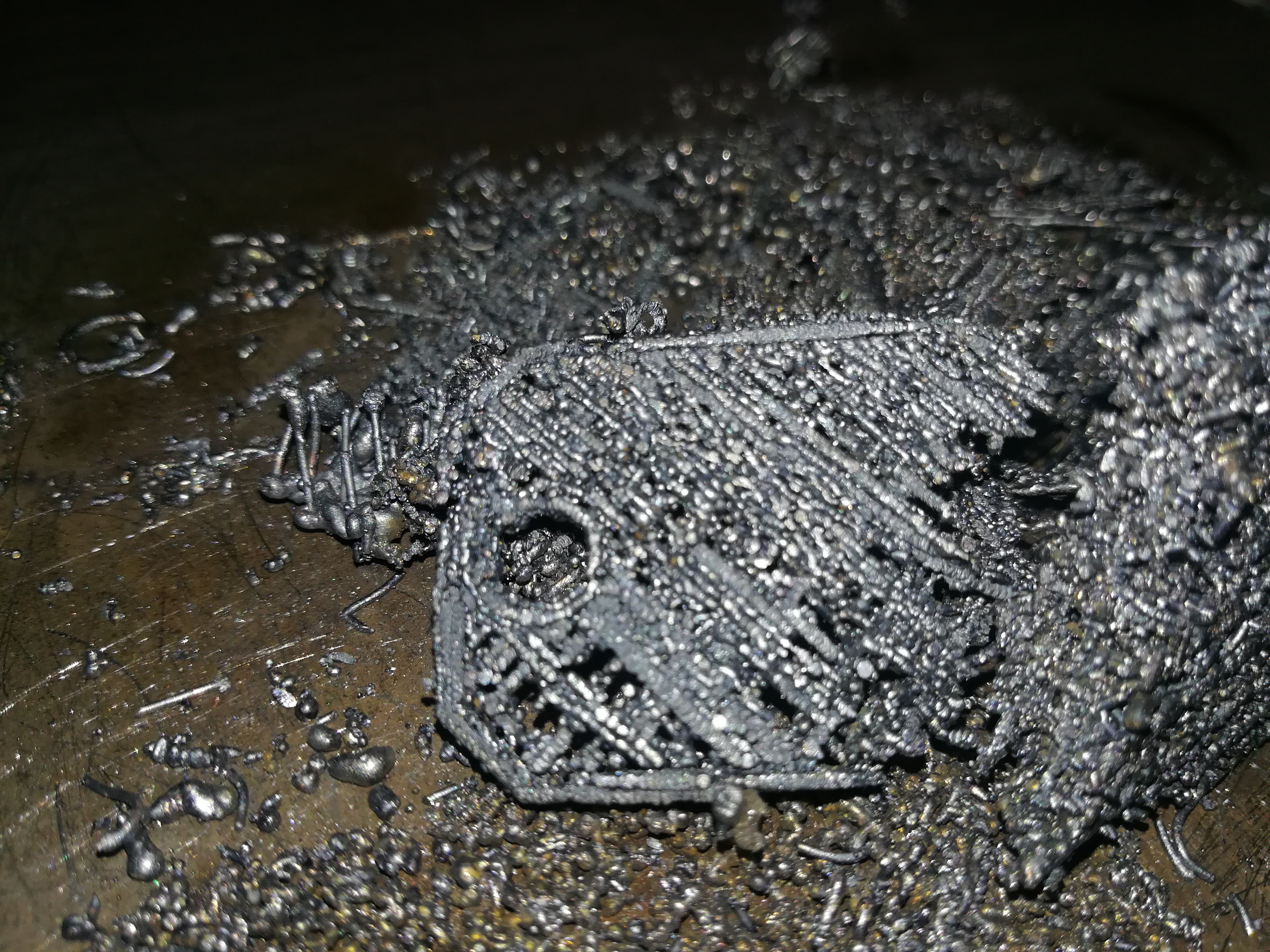
Today I tested the printer for the first time with random settings. I guess the extrusion rate and the distance between buildplate and nozzle was too high. Maybe with better settings the print quality can be improved to get usable results and so maybe the operation will switch form some sort of firework to a smooth glowing wire laying process.
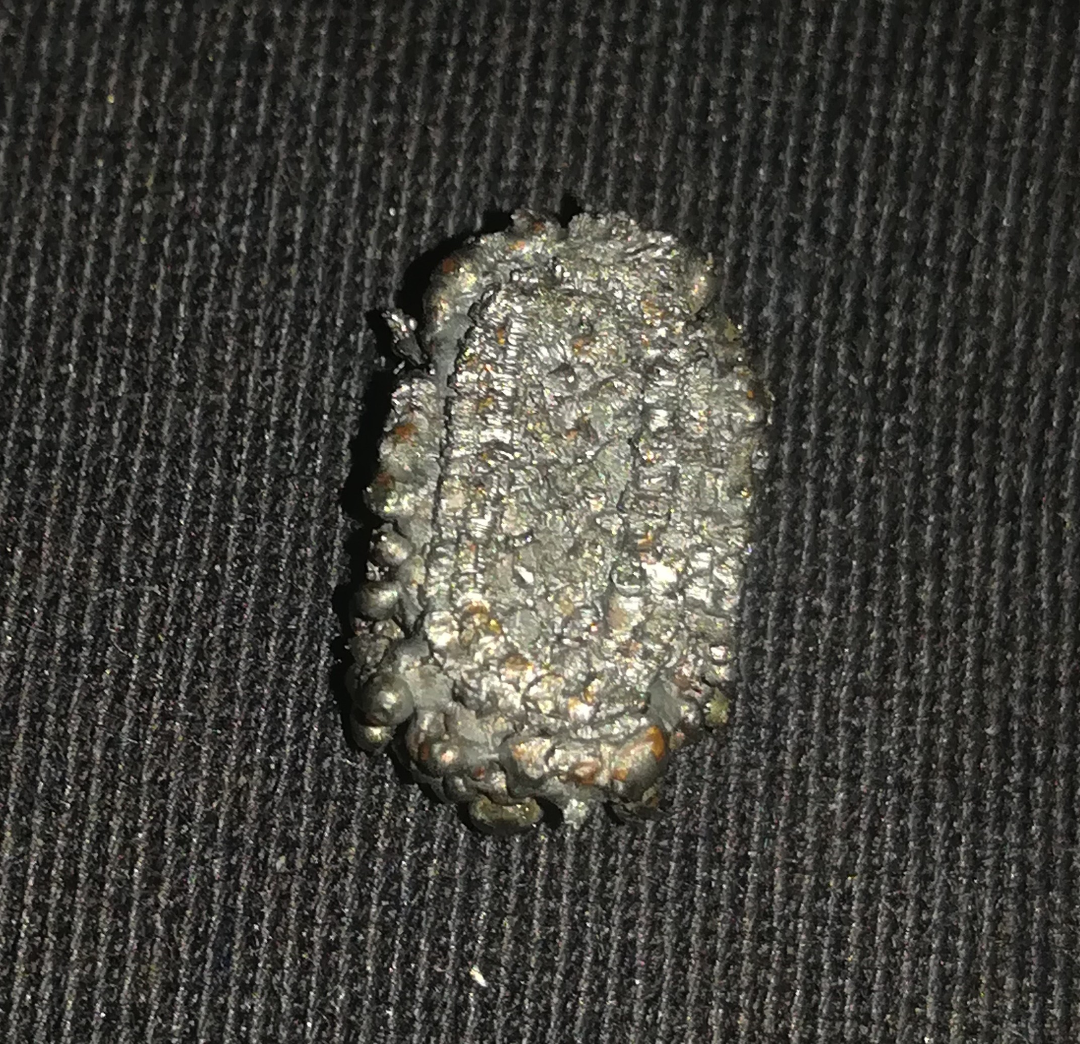
Top and bottom of the printed object
![]()
![]()