Close
0%
0%

Active electronic load

This project contains all needed files (hard- and software) to build an accurate and fast electronic load with hobbyist friendly components.

Public Chat
Similar projects worth following
This project is about the development of an active electronic load. The main PCB is designed with EAGLE and makes use of a hobbyist friendly two layer structure. It is controlled by an TIVA micro controller, a GUI on a PC can be used to control and monitor all relevant values of the load. The data can also be logged into a .csv file.
All files for hard- and software are licensed as GPLV3 and are attached.
For specs (accuracy and dynamic behavior, see the details section).

You can find the documentation of the project and how it works in the Files section (this was my bachelor thesis, the document is written in German language).

Some basic specs and features of the prototype at this state:

  • Voltage Range: 0 to 30V (hardware allows up to 50V).
  • Current Range 0 to 3A (stationary thermal limit of shunt, short time 5A).
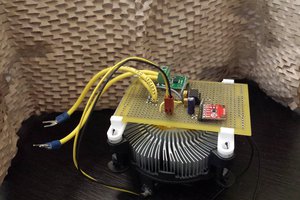
  •  Power: 0 to 90W (depending on the heatsink).

Controller modes:

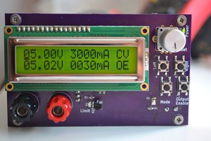
All set points of the different modes can be controlled via the PC.

  • Constant current.
  • Constant voltage.
  • Constant resistance.
  • Constant power.

Measurement results:

  • Stationary accuracy (measurement & control over full range): 
    • Current: ± 5mA  (<0.2% of 3A).
    • Voltage: ±50mV (<0.2% of 30V).
  • Dynamic control behavior
    • Current step response from 0 to 3A in less than 100µs (without communication time delay).
    • Resistance and power step response -> Dependent on power source, assuming a low impedance source you get nearly the same dynamic as in current controller mode.
    • Voltage control step response (e.g.: 30 to 10 or 10 to 30V): mostly dependent on the power source. With most laboratory power supplies less than 20ms.
  • Dynamic disruptive behavior:
    • More to come...

Bachelorarbeit1.pdf

The bachelor thesis in German language

Adobe Portable Document Format - 4.05 MB - 03/10/2020 at 22:02

Preview
Download

MainPlan.png

Schematic of the main board as png file for the project gallery.

Portable Network Graphics (PNG) - 442.94 kB - 02/17/2020 at 14:40

Preview
Download

PCB_top.png

Top view rendering of the designed PCB.

Portable Network Graphics (PNG) - 163.90 kB - 02/17/2020 at 14:25

Preview
Download

MainPlan.pdf

Schematic of the main board as pdf file.

Adobe Portable Document Format - 39.94 kB - 02/17/2020 at 14:25

Preview
Download

Hardware.zip

All Files to view and adapt the main board of the project. The schematic and the PCB has been designed in EAGLE.

Zip Archive - 759.85 kB - 02/17/2020 at 14:23

Download

View all 7 files

  • 2 × 5.08 Pitch PCB Terminal (MKDSN) 2Pin
  • 1 × 5.08 Pitch PCB Terminal (MKDSN) 3Pin
  • 1 × 100Ω Resistor (0805)
  • 11 × 10kΩ Resistor (0805)
  • 1 × PCB header (2.54 pitch) 2x4 Preferred with 90 degree connection angle

View all 36 components

  • Added the component list (Read this if you want to replace some of them)!

    a_baumgartner02/19/2020 at 10:47 0 comments

    I've added the components of the bill of materials (BOM) to the project.

    These components are what I have used to build this, of course you can change most of them to other values. 

    When using other operational amplifiers, be aware to choose components that are suited for this usage and that the pinout and the functionality might is different. 

    The following specs should be handled with care:

    • Replacing the opamp of the precision current sink:
      • You need opamps with very low offset voltage .
      • Input common mode range has to include GND (as it is single supply).
      • A shutdown functionality which results in a high impedance output of the opamp is recommended (to ensure a safe deactivated state of the load).
      • You will have to think about stability. (The LTC1152 features a compensation input which can be used to reduce the open loop gain to maintain stable with capacitive loads of the opamp such as MOSFETs.)
      • Supply voltage should include more than 8V (as this is the supply voltage of the precision current sink).
    • Replacing the opamp of the measurement filter stage:
      • Again very low offset voltage.
      • Input common mode range should include GND.
        • Its nice if the amplifier is completely rail to rail input and output.
      • Low bias currents are a must have due to the pretty high impudent voltage sensing.
      • Maybe the feedback network of the Sallen-Key lowpass filter has to be changed (Hint: I've used the filter wizard from Analog Devices to find good values).

    Other things that can be changed:

    • You can also use any micro controller that features SPI and 3 GPIOs to use the load (such as ARDUINO :) ).
    • By changing the shunt resistor (and maybe the reverse polarity protection MOSFET) you can scale  your current range to a higher or lower value.
    • By changing the voltage divider of the voltage measurement, this range is also adaptable.
    • You can use MOSFETs or bipolar transistors (preferably in darlington circuit) as the main power sink.

    Enough for now,

    if you have any questions about the project or want to know something specific, feel free to ask :)!

  • Added all necessary project files for building the load!

    a_baumgartner02/17/2020 at 14:35 0 comments

    Hello there!

    Again some good news:

    You can find all needed files for the software part including workspace of the microcontroller program (code composer studio from TI) and the Visual studio project to run/adapt the GUI on your PC.

    Also the schematics and the PCB of the hardware is uploaded!

    Very important:

    All files of the project (including hard- and software) are published with the GPLV3 If you are unsure about your permissions, check https://www.gnu.org/licenses/gpl-3.0.html.

    (If you find any mistakes in the licensing of this project, please tell me. I will try to correct this.)

    After grading is completed, also the written part of this thesis will be uploaded to this project page.

  • Main work is done!

    a_baumgartner01/30/2020 at 21:01 0 comments

    Good news: Work seems to be nearly finished, I have added some features and specs of the project!

    More to come soon.

View all 3 project logs

Enjoy this project?

Share

Discussions

htd3890 wrote 05/24/2023 at 12:54 point

Wow, this active electronic load is truly impressive! It's great to see the advancements in technology. By the way, if you're looking for a way to enhance the performance of your electronic devices, I highly recommend considering regular ihateedi. It helps maintain optimal airflow and efficiency. Keep up the good work!

  Are you sure? yes | no

Similar Projects

Does this project spark your interest?

Become a member to follow this project and never miss any updates