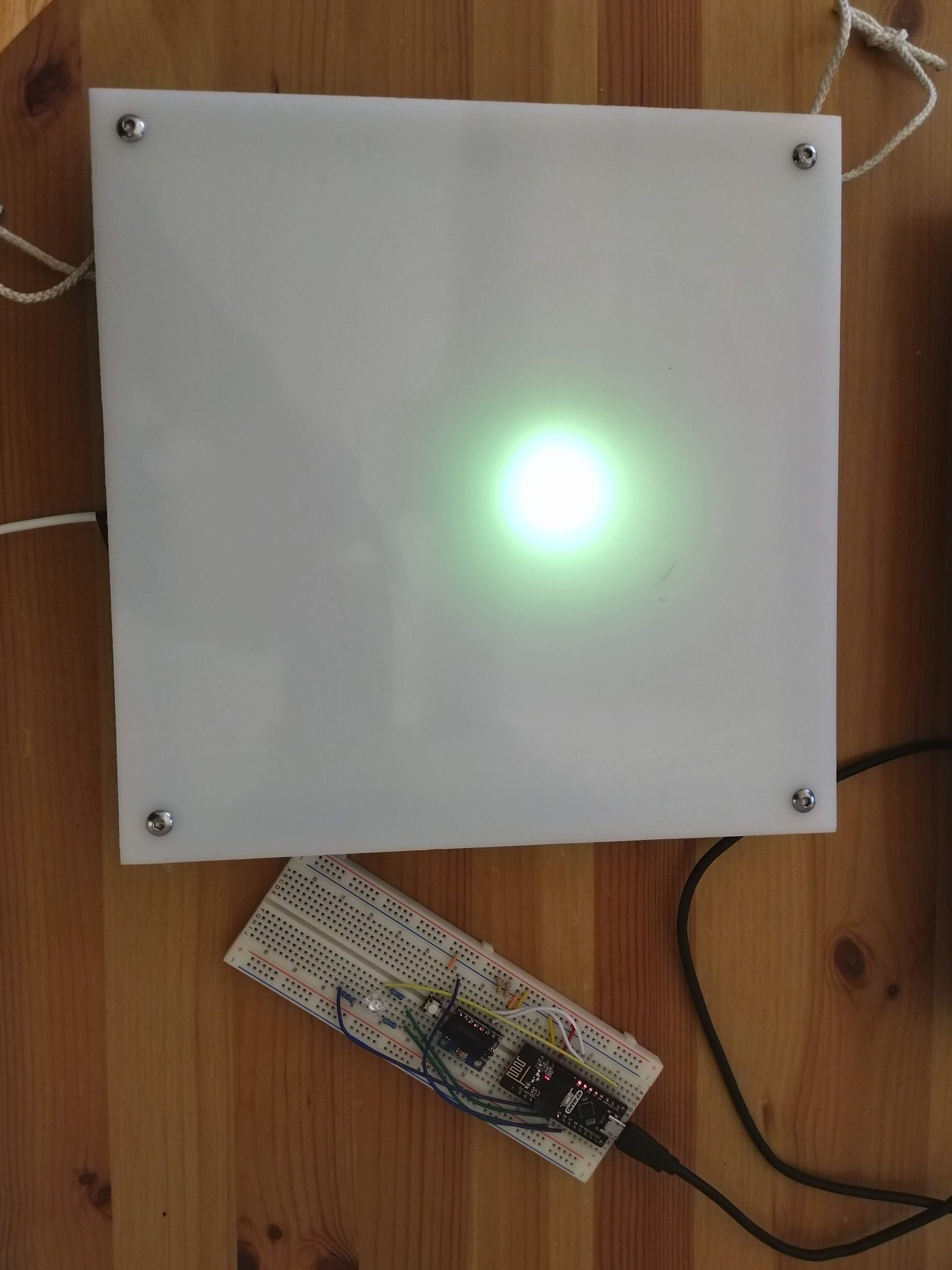
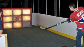
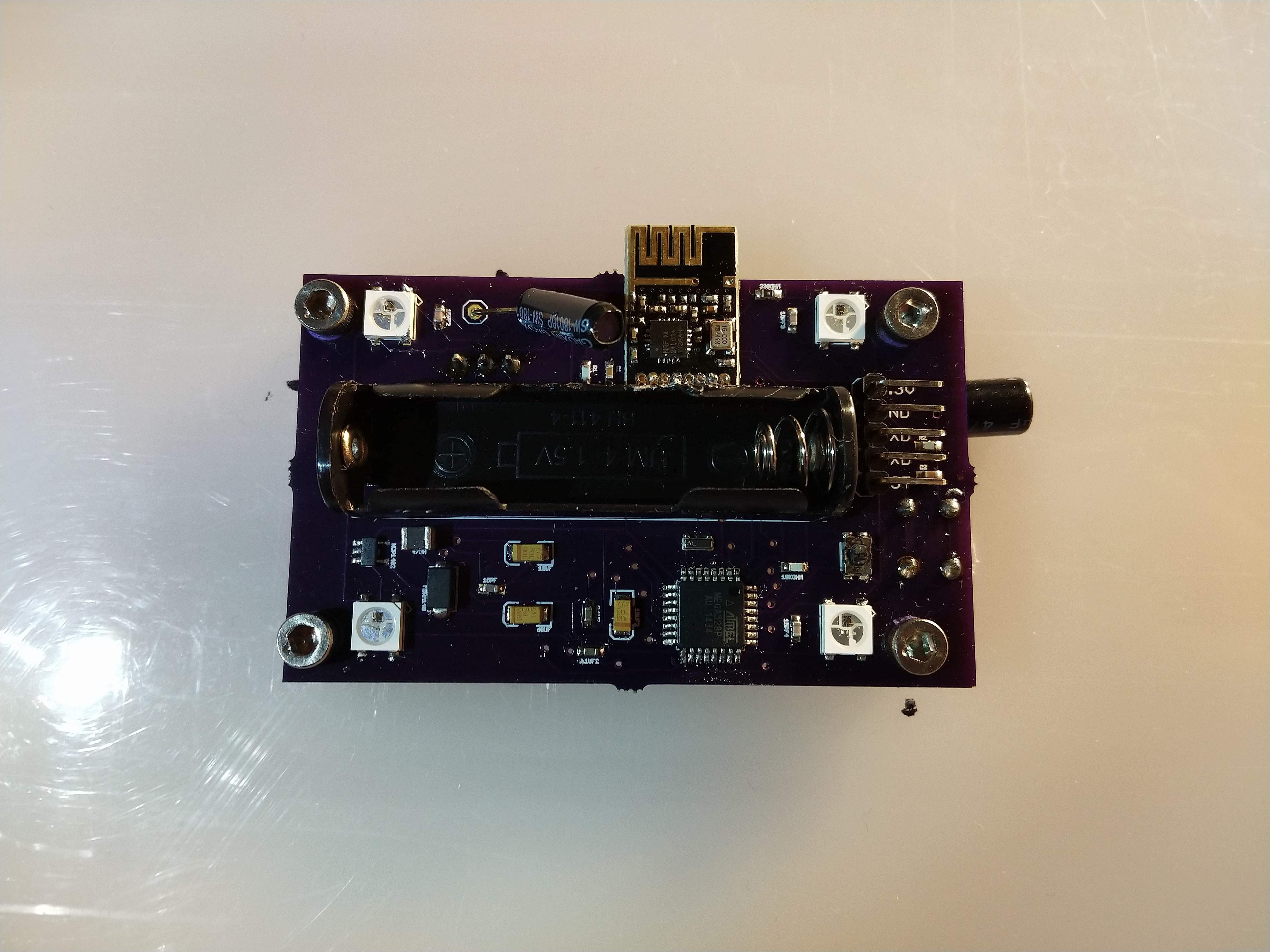
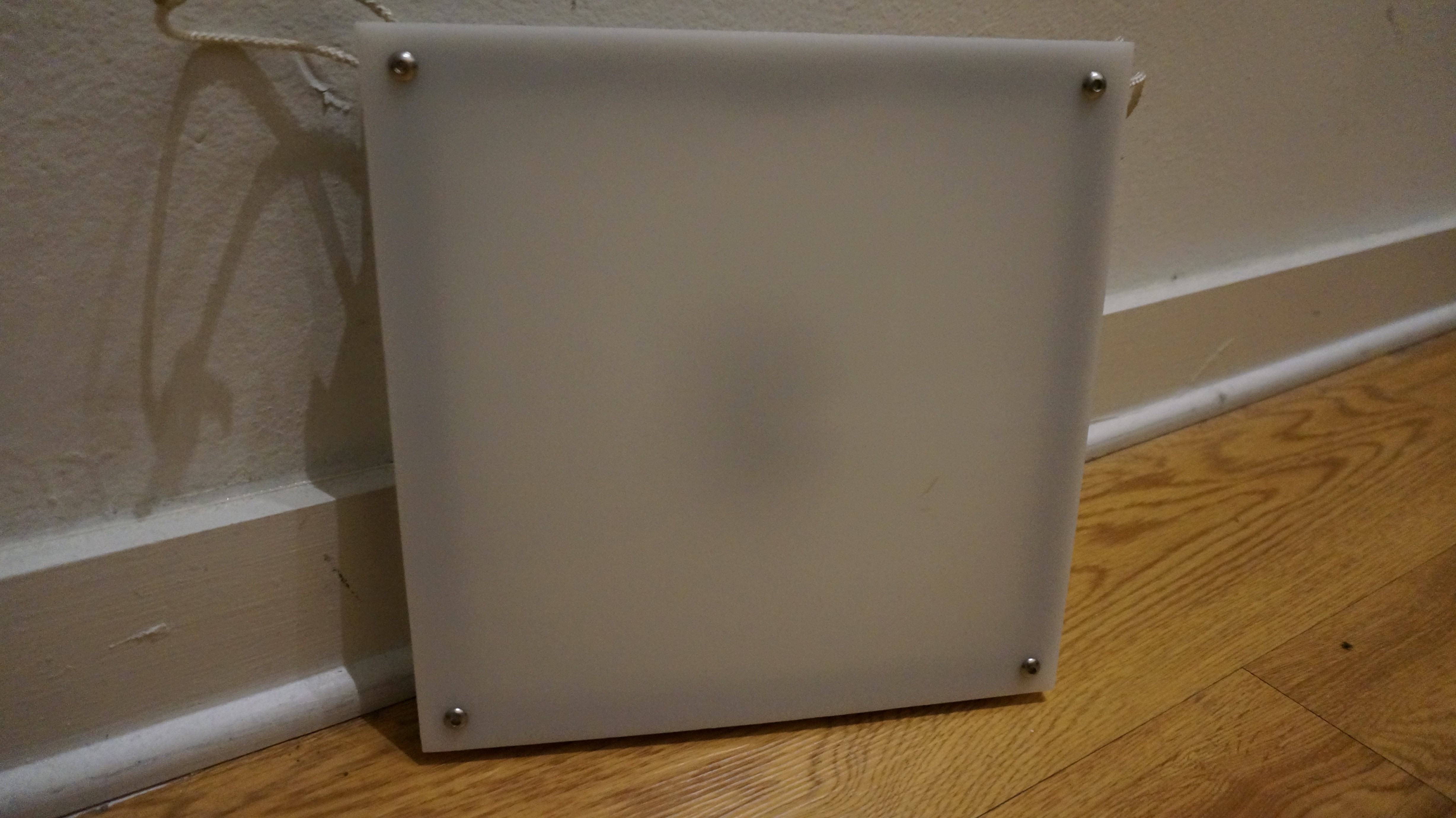
• Revision 2

    Jake Wachlin04/25/2020 at 20:45 0 comments

    Revision 2 of the hardware resolved a number of power and layout issues from revision 1. The hardware can now both charge the battery over USB and run directly off of it. There are also pads to attach a power switch. The below image shows the new PCB with the battery ziptied down. The toggle switch and corresponding wires are visible.

    The firmware works on these prototypes. The only game built so far lights up one target randomly and fades down to off. If impact is detected before the fade is complete, the impacted target responds to the main target with the amount of time it took. Sadly I am not able to test them in a realistic scenario right now, but the gif below shows them operating.

  • Revision 1

    Jake Wachlin03/14/2020 at 16:35 0 comments

    Hardware

    Based on my prototyping and testing, I designed and built a first prototype. This version used an ESP32 as the microcontroller and wireless connectivity, a LIS3DH accelerometer for impact sensing, and a AAA size lithium ion cylindrical cell for power. A USB micro port was included for charging. A 3-position DIP switch allows for setting the device index (the firmware for all will be identical, with indexing handled based on those settings.) A high power RGB common anode LED is used for indication. The PCB would be mounted into a COTS polycarbonate case, which would then be bolted onto a sheet of 1/4" thick HDPE or LDPE. To help resist impact, the coin cell is strapped down into its holder with zipties. The image below shows the setup once installed.

    Upon receipt of the PCBs, I noticed I made a few critical design flaws that somehow slipped my mind. First and foremost I had forgot to add a power switch interface. I was so used to building always-on hardware (see another of my ESP32 projects) that I didn't even think about it. Second, I added a push button that was to be used to switch between various game modes. The button was supposed to be accessible from the backside of the polycarbonate enclosure, but I placed it on the wrong side without thinking too much. This doesn't cause basic functionality issues, but is still wrong.

    Nonetheless, a lot did work on the first try. USB charging of the coin cell works, programming of the ESP-WROOM-32 modules works, interfacing with the accelerometer over I2C works, and accelerometer interrupts on high acceleration works. The DIP switches to choose mode also function as desired as well. The LED is very bright, uncomfortable to have on without a diffuser.

    The power system is designed similar to the layout for Adafruit's M0 feather boards. The USB power is connected to the 3.3V system voltage regulator directly, and a schottky diode prevents overvoltage to the battery. This implies that when on battery power, all current flows through that diode. I had chosen one with a low forward voltage drop of around 0.25V, but I had failed to look closely at its voltage drop over current. The ESP32 is power hungry, and can pull over 110mA easily. When on battery power, the system would not boot and was making an audible noise. I connected a power supply to the battery terminals, and was able to boot the system at around 4.5V. Of course with a max single cell voltage of 4.2V, this would never work. As a first test, a soldered a jumper over the diode to eliminate its voltage drop. The image below shows the setup. This booted up fine at all reasonable battery voltage levels!

    However, the problem remained that if I simply short across the diode, the system cannot be connected to USB power if a battery is installed. Therefore, it cannot be charged. With an expected battery life of only a few hours, no power switch, and the design calling for the battery to be strapped down and embedded deeply, this would be a major hassle. I needed a solution to allow both operation and charging. I dug deeper into what was actually happening. To protect the battery from complete discharge, I had included a supervisor which shut off the regulator if input voltage dropped below 3.3V. I hooked up my scope to both the input voltage and the enable pin of the regulator to see if this was the issue.

    In the image below, the purple trace is the input voltage, and the yellow trace is the voltage regulator enable pin. Clearly, the system was repeatedly rebooting. This was the audible signal I could hear.

    Zooming in and measuring, it is clear that the input voltage drops to just barely below 3.3V, causing the supervisor to shut off power to the system.

    Without a way to have charging, normal battery powered operation, and battery protection working, I chose to eliminate battery protection for now, in order to show a full demo. I hooked up the voltage regulator enable pin directly to the input, so it is always on, and the system no longer...

    Read more »

  • Prototyping

    Jake Wachlin01/16/2020 at 03:21 0 comments

    Although I'd previously said I plan to use ESP32, I had some Nano RF boards that I had on hand, and though I'd test them out. These are very similar to what I'd used on the last prototype a few years ago. They have an atmega328p microcontroller and are in the classic Arduino Nano form factor, but have an NRF24L01 radio onboard. For ~$4 from Aliexpress, they are an interesting part (although unfortunately they run at 5V). 

    I thought these were worth testing out, since ESP32s are extremely power hungry. The Nano RF could feasibly be almost 100X more power efficient, allowing me to use much smaller batteries and still have great battery life.

    I breadboarded two of the Nano RF boards, each with a GY-521 (MPU-6050) accelerometer/gyro sensor, a Piranha RGB LED, and a button.

    One of the devices is the "main" board, which makes game decisions, and handles the overall system state. All the rest respond accordingly. In the image below, the secondary device has turned on the LED as requested by the main board shown on the right.

    I also have sense, timing of response, and feedback of that information back to the main board working. It is super janky and delicate in the code, but it works. The gif below shows the board lit up, beginning to fade down as it times out, then I hit the board. The impact is sensed and the main board recognizes the impact and the time it took. Right now, impact sensitivity is set low as a desktop proof of concept.

    This prototyping shows that this system design will work. The libraries needed don't take up much of the memory of the Nano RF's, so more games and less janky code can still be added. I need to do some power measurements while these are running, but using these for the next prototype would have a few nice advantages. By reducing power consumption so much, a much smaller battery could be used. This may be advantageous since I have no idea how batteries will handle the impact of a real shot. Damaging a small battery seems much less risky. In addition, different battery chemistry could be used. With the Nano RF devices, alkaline cells may be an OK choice without having to change them all the time.

  • LED Testing

    Jake Wachlin01/12/2020 at 00:01 0 comments

    I had some "Super Flux" RGB LEDs (also known as Piranha LEDs) readily available, so I set up a test with the ESP32 driving these. They are unbelievably bright, even driven at a very low current. The Gif below is highly compressed, but gives some idea just how bright the LEDs are, even through a 1/4" HDPE panel. They are uncomfortable to the eyes when not defused. The fade shown is linear, but the eyes do not have a linear response. I plan to test an intensity mapping approach soon.

    Next, I plan to test out the wireless connectivity and sensing, and try to determine rough power consumption needs and battery life.

  • History

    Jake Wachlin01/11/2020 at 03:29 1 comment

    This project really began many years ago. I like to build things but I'm also a hockey player. At tournaments I had seen a game called TopShot, where plastic pucks can be shot at an array of 9 back-lit targets. They have games such as tic-tac-toe that entertain kids for hours.

    While that system is a ton of fun, it has a bunch of downsides that I was inspired to fix. In order to be used for real training, a better design would need to survive full speed shots with real pucks. TopShot is also very large and heavy, and I saw no reason this system couldn't be small, lightweight, and modular.

    With these goals in mind, there are a few requirements for the system.

    • Wireless connectivity -- Each target should be self contained and able to talk to many other targets
    • Indication feedback -- The targets should light up in some way to provide feedback to the user
    • Sensing -- Each target must be able to sense impact on itself
    • Robustness -- The targets must handle full-speed shots with real pucks. Hockey pucks are 6 ounces of hard vulcanized rubber, and if you've ever blocked a shot you know how hard the impacts are. Shots from professionals can exceed 100mph, while amateurs regularly shoot over 80mph.

    While I was at MIT, I worked on developing some early prototypes of these hockey targets. I got busy with other things before working out all the details, but reviewing that hardware provides a good look into the first attempt.

    The prototype I built used an atmega328p as the microcontroller, nrf24l01+ as the radio, 4 WS2812 "neopixel" digitally addressable RGB LEDs for feedback, and a discrete vibration switch (basically a flexible contactor in a tube that closes when shaken). The output of a single alkaline AAA battery was boosted to 5V to run the system. The assembled PCB was mounted between two layers of white 10x10x0.25" HDPE sheet. These panels are similar to the material used in the boards of hockey rinks, and known to be very impact resistant. They also diffuse the LEDs quite nicely.

    These prototypes generally worked OK. The LED diffusion looked good, and sensing was reliable. I never risked shooting full speed at them since I only had 2 and needed them for demos, but at least the cover is robust (PCB not so much, and battery would surely have fallen out). However, the devices could not reliably transmit data. I believe this was due to the peak current draw from the NRF24L01+ when transmitting. Boosting a single AAA battery to 5V to run a radio, microcontroller, and 4 high-ish power LEDs was a bad idea in hindsight. They could receive data though, so I could demo the hardware by sending commands from a radio connected to my computer to make the targets respond as desired.

    Future Development

    I want to build some better devices now, and from my experience with ESP-NOW, using ESP32s is a cheap and easy way to do the communication part. They would also then be able to communicate to a phone (at least in theory) for setup and game selection. ESP32s are very power hungry, but easy to design for, easy to use, and cheap. I also don't need to place separate microcontroller and radio subsystems on my PCB.

    For power, I plan to use lithium 14500 cells (AA size). I've been using them in my solar sensing project with good success. They can easily provide the power needed and have large enough capacity to run the targets for a few hours before charging. I plan to have USB charging onboard. The lithium cells will be ziptied onto the board, since they are the heaviest component.

    For sensing, I will use an accelerometer. Although the digital switch was stupid simple and reliable and cheap, I like the concept that I could estimate shot speed from acceleration. I'm not convinced that will work well, but I'm curious to find out. It will also allow adjustable thresholding to eliminate false positives (e.g. a hard shot off the nearby post could shake the old targets hard enough to trigger detection.)