 Erik van Zijst
The full write-up is on Medium:
Lots of additional photos:
The Gerbers are up on OshPark:
- clock: https://oshpark.com/shared_projects/OE6N7Z1x
- MEMS addon: https://oshpark.com/shared_projects/KbQrsVwL
The KiCad schematics and PCB layout, as well as Gerbers are up on GitHub:
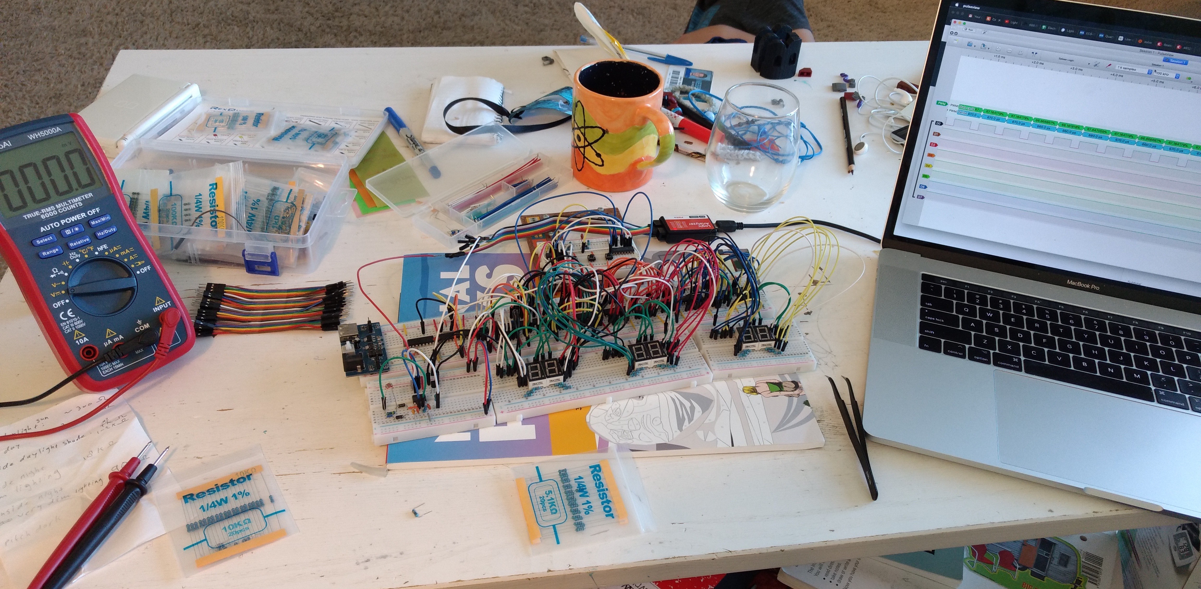
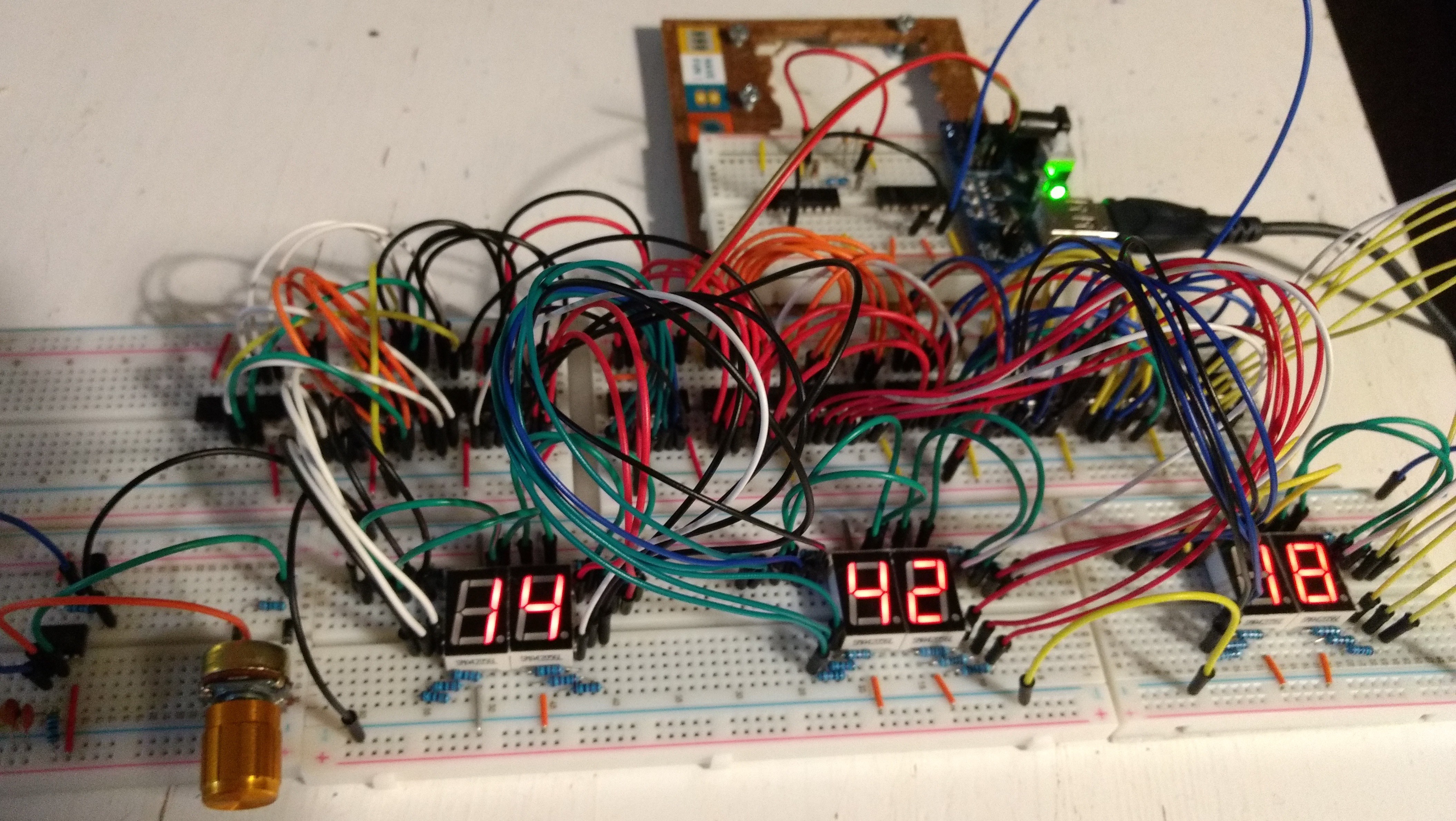
This project started on a (series of) breadboards
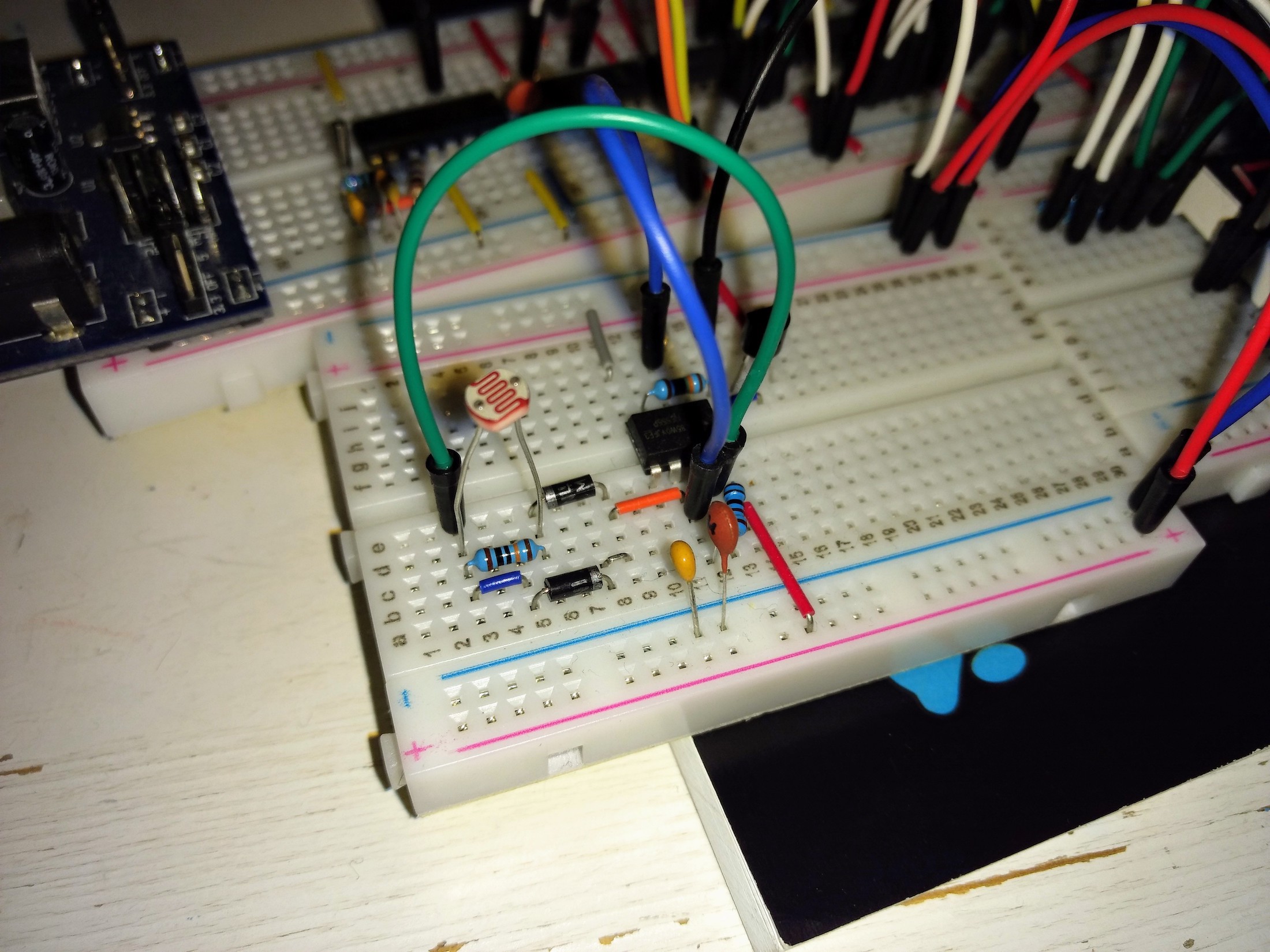
The low-tech LDR-driven PWM adjusting the display brightness uses a 555 timer.
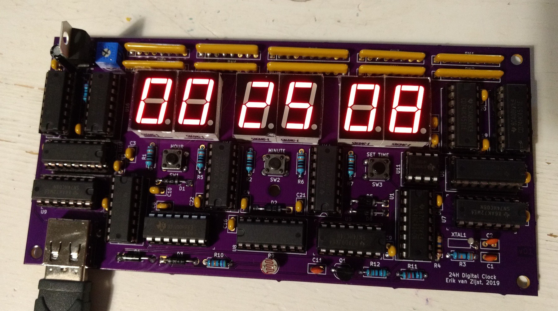
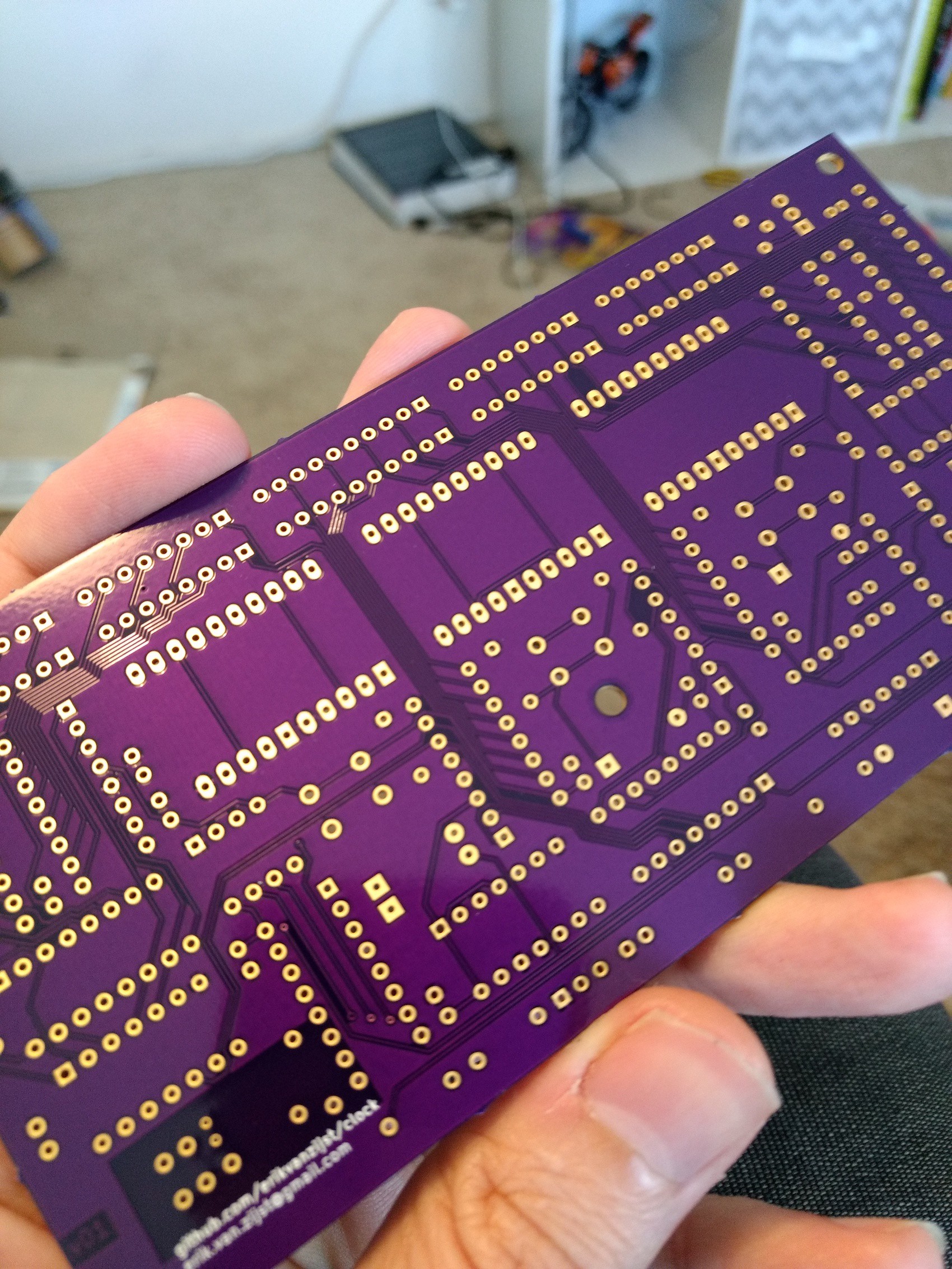 My first real PCB. So much anticipation soldering everything up, hoping I hadn't made any mistakes in the layout.
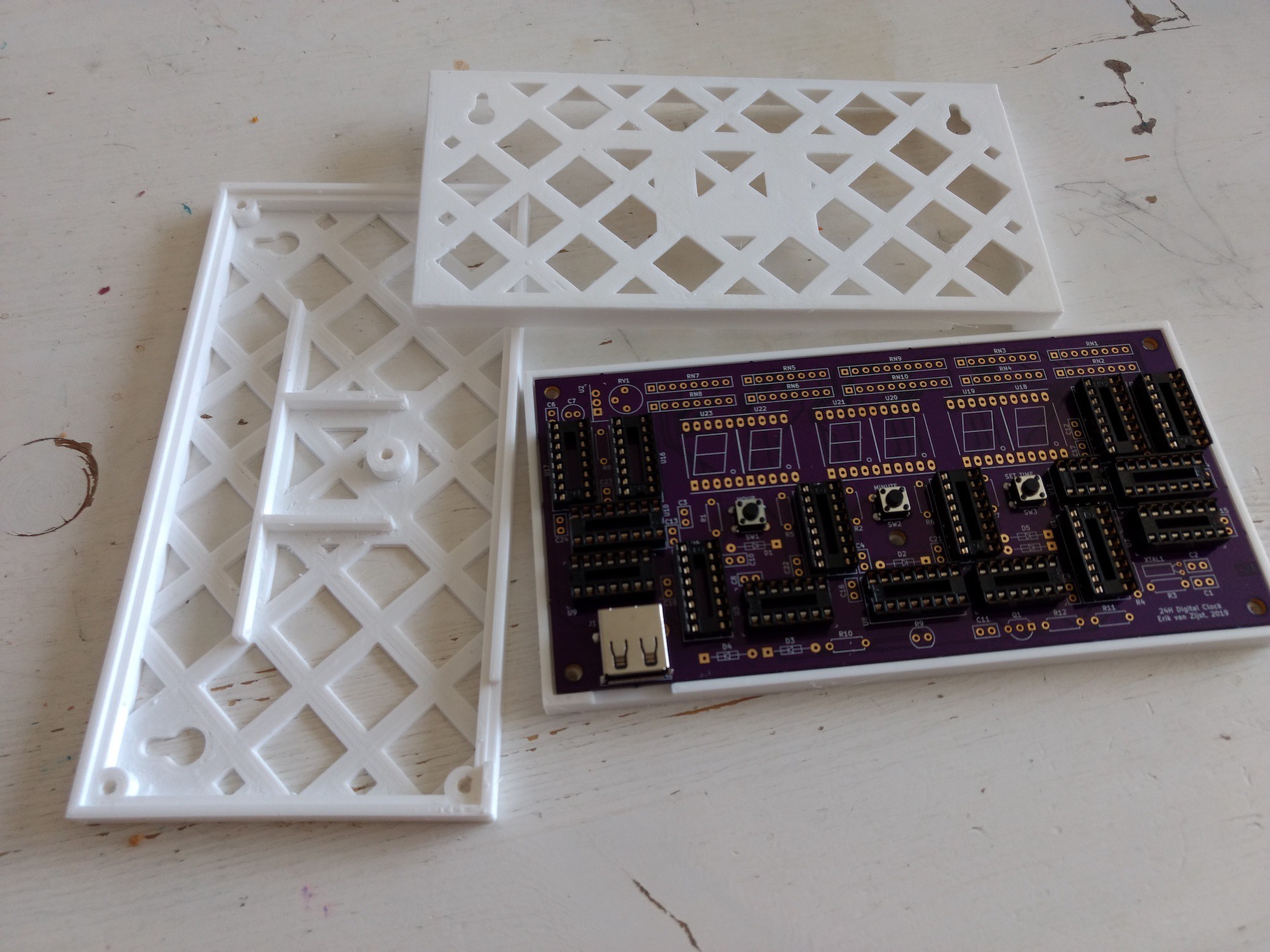
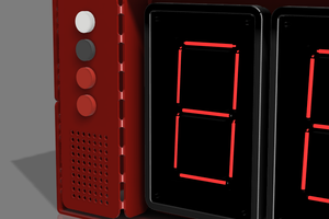
I created a minimalist 3D-printed wall-mounting frame.
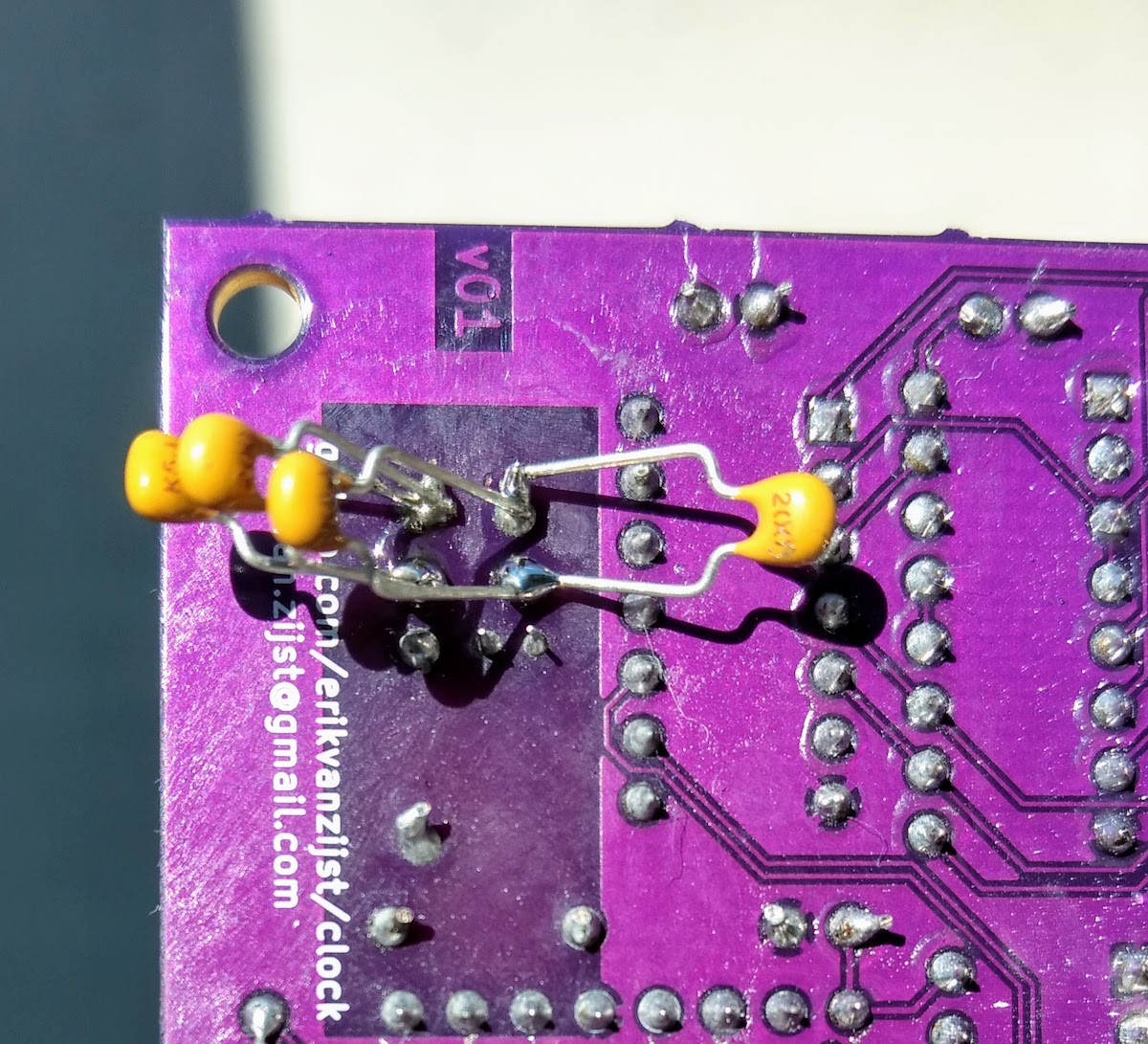
Turns out debugging hardware is a lot more painful and slow than software!
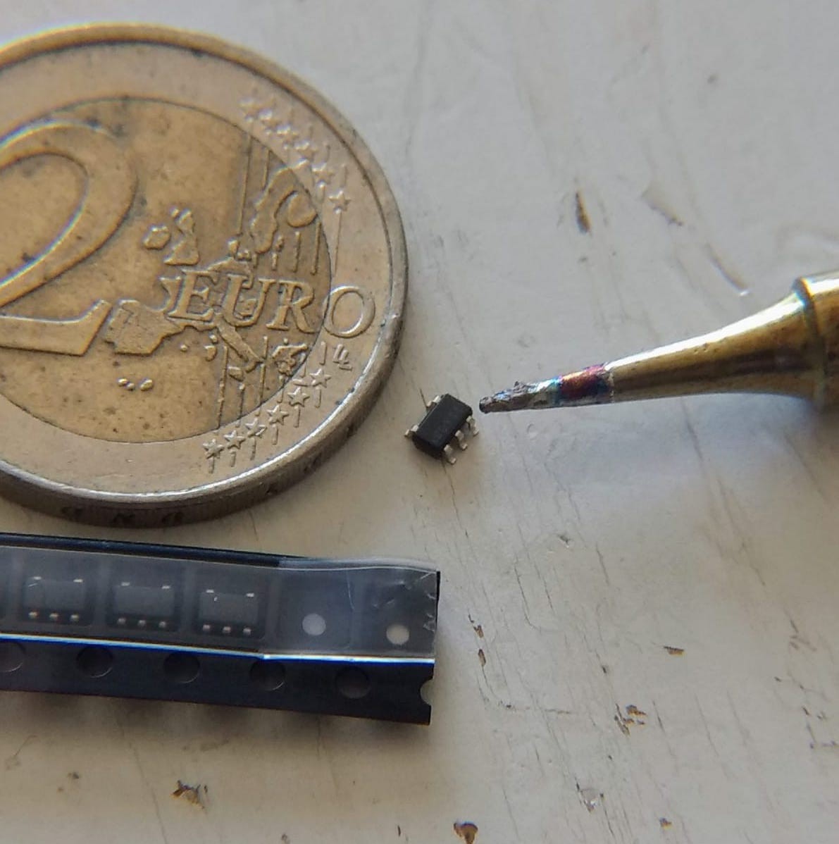
MEMS oscillators don't seem to come in through-hole, so this became my SMT trial-by-fire.
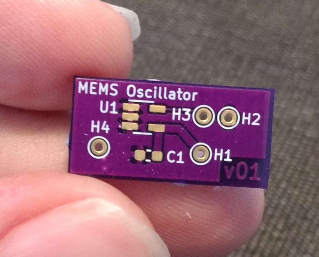
When the crystal circuit proved unreliable I ultimately decided a "patch" was necessary and I created a tiny little addon board with a MEMS oscillator that would slot into the crystal circuit's through holes.
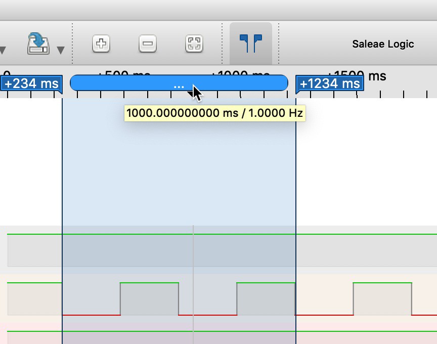
Using the logic analyzer to measure the accuracy.
More details at https://medium.com/@erikvanzijst/a-digital-quartz-clock-from-scratch-a80ec5e427


 Madison
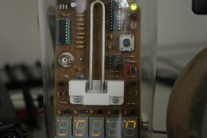
 Kris Slyka
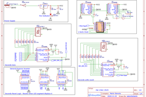
 Mario Gianota
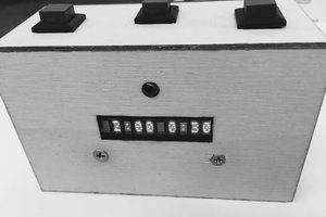
 Jimmy Patrick
Great project! How MEMS oscillator stays in time?