 K.C. Lee
Motivation:
I sometime play games into the night without realizing how late it is. I need a clock below my monitor that is non-distracting, large, easy to read in my peripheral vision. Also it would be ideal if is set and forget i.e. accurate enough and handle silly DST time changes.
Additional pages for this project on HaD:
https://hackaday.io/page/6687-stm8-led-clock - more project details
https://hackaday.io/pages/10708 - test results
External Project page:
- https://hw-by-design.blogspot.com/2019/11/stm8-led-clock-part-1.html
- https://hw-by-design.blogspot.com/2020/01/stm8-led-clock-part-2.html
- My timer project code was used in this project. The UI has been stripped down. The new features NCO, date and DST features have been back ported to the timer.
Github: https://github.com/FPGA-Computer/LED-Clock
User interface
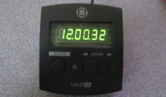
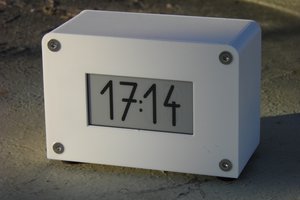
The clock and display time:
The arrows key switches between the time and date display. The date display uses a different format to distinguish the modes. The 7 segment LED can only show a limited set of characters and have to make do with some approximations.

e.g. Th(ursday) 16 Jan is shown below.
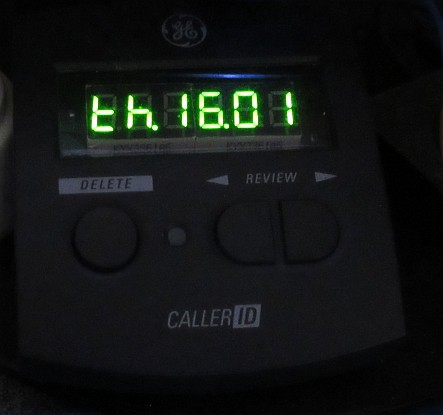
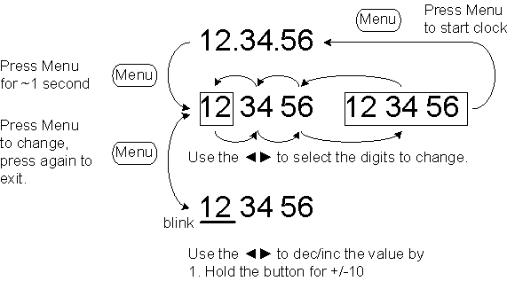
Time (and similarly date) can be set using 3 buttons.
Hardware description:
Instead of using the usual RTC modules used by other projects, the RTC is implemented in firmware with features such as Daylight Saving Time. The RTC code can be adapted for oddball clocks that uses different units of time. e.g. Metric time or Mars time.
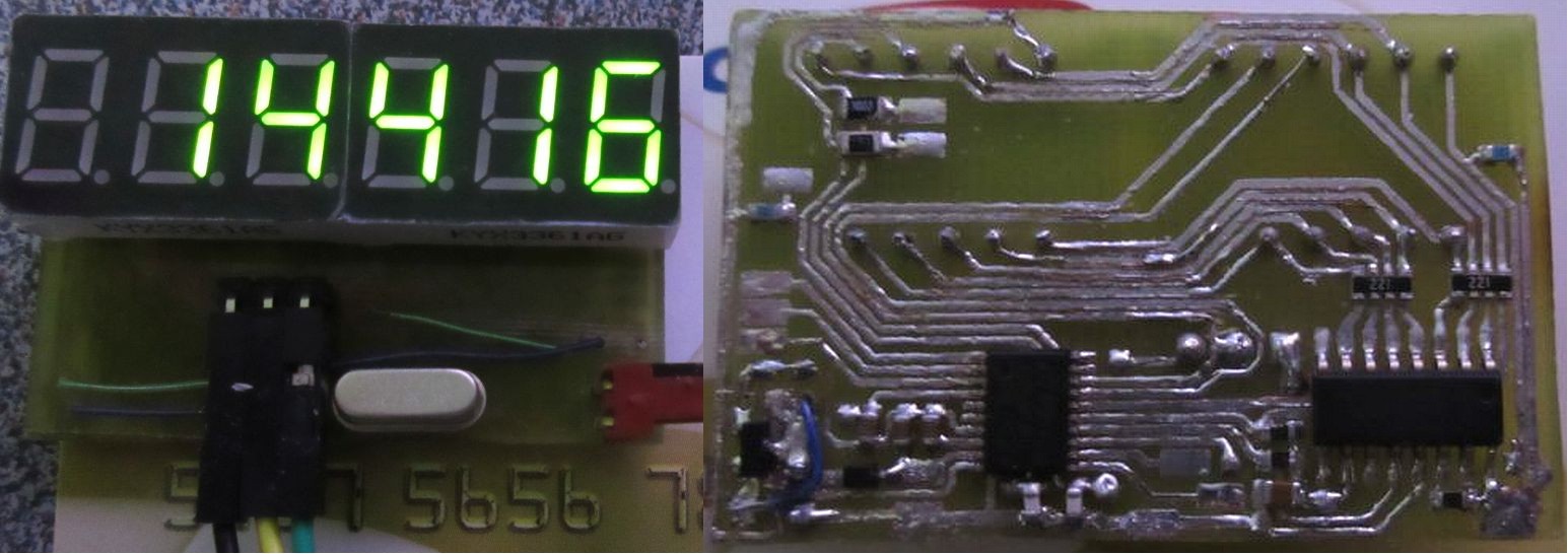
The clock doesn't require an ultra accurate crystal. As long as it has a very stable frequency, then the tolerance can be calibrated out. I used a common AT-cut 12MHz crystal as the frequency source.
If clock is used in a home environment with temperature controlled, chances are that the temperature variation is small enough to get away without using a TXCO. e.g. Heater set to 21C and air condition to 25C means that the variation is about 4C.
There is only a very narrow frequency range that you can shift a crystal by the load capacitance and a trimmer capacitor doesn't make fine adjustment predictable nor repeatable.
A 16-bit timer in the STM8 generates a 20Hz IRQ. A more accurate 10Hz is then generated from using a 24-bit Numerically-controlled oscillator (NCO) implemented in firmware.
e.g. if your 20Hz is +50ppm fast = 20.001Hz, 10Hz can be generated by dividing it by 2.0001.
NCO can perform fractional frequency division by keeping track of the phase in an accumulator. Don't let the name fool you, this 3 extra lines of code is all that's needed for very fine frequency adjustments!
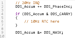
The 10Hz is used by the RTC code to update the time, date and implement the Daylight Saving Time (DST) for North America.
(repost from https://hackaday.io/page/6687-stm8-led-clock)
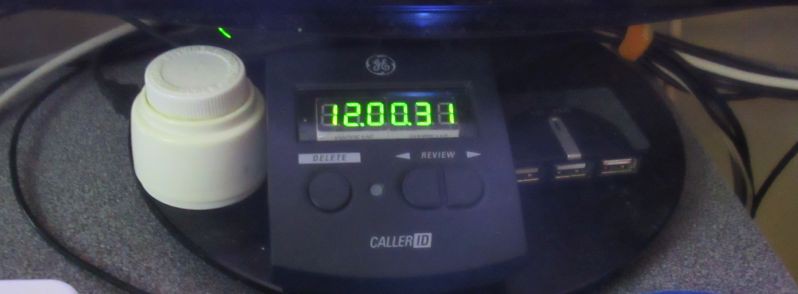
I made a digital clock. Originally I planned to use a VFD, but the user interface on a 4 digits would be too limiting. I used a STM8S003, 74HC595 and a couple of the cheap green 7 segment displays. The display efficiency is actually not bad as the entire clock runs on 5V at ~20mA.
The LED driver is on a separate rail. A supercap allows the STM8 to work for a few minutes during a power failure.
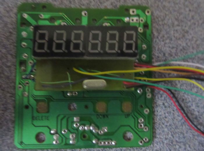
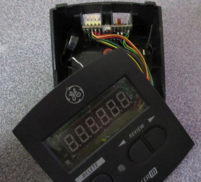
The PCB is wired to the original (stripped) Caller ID PCB to use existing buttons. The same GPIO for the common cathode driver when off-duty is used for polling the buttons.
I could have used the STM8 alone to drive the display. By adding the 74HC595, I freed up a few GPIO lines for future expansion.
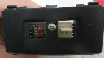
External I/O
UART, I2C, a Timer pin, 5V power and the hardware debug interface (SWIM) are connected to the headers on an I/O panel PCB using the existing RJ11 cutouts. I have since changed the power connector to a MicroUSB as it has much better latching.
Side by side view of the old traveler's Casio clock it is replacing as it...
Read more »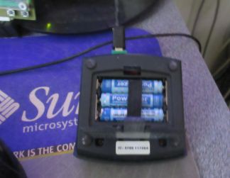


 Daniel Zilinec
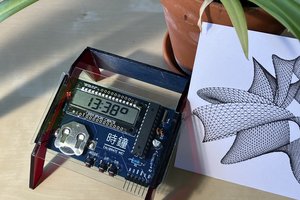
 Gabor
Gabor
 mircemk
I too love an accurate clock, and this is pretty impressive. But one thing I'd pay dearly for more than accuracy is synchronization - I hate that the microwave clock and the range clock seem to be in time zones separated by a couple of seconds. The clock in my high school were all synchronized, and that was 40 years ago. You'd think we'd have figured this out by now.
</rant>