 Selali Adobor
I actually built 2 development boards for this project.
The original was based on a much smaller 8 pin ESP8266 module:
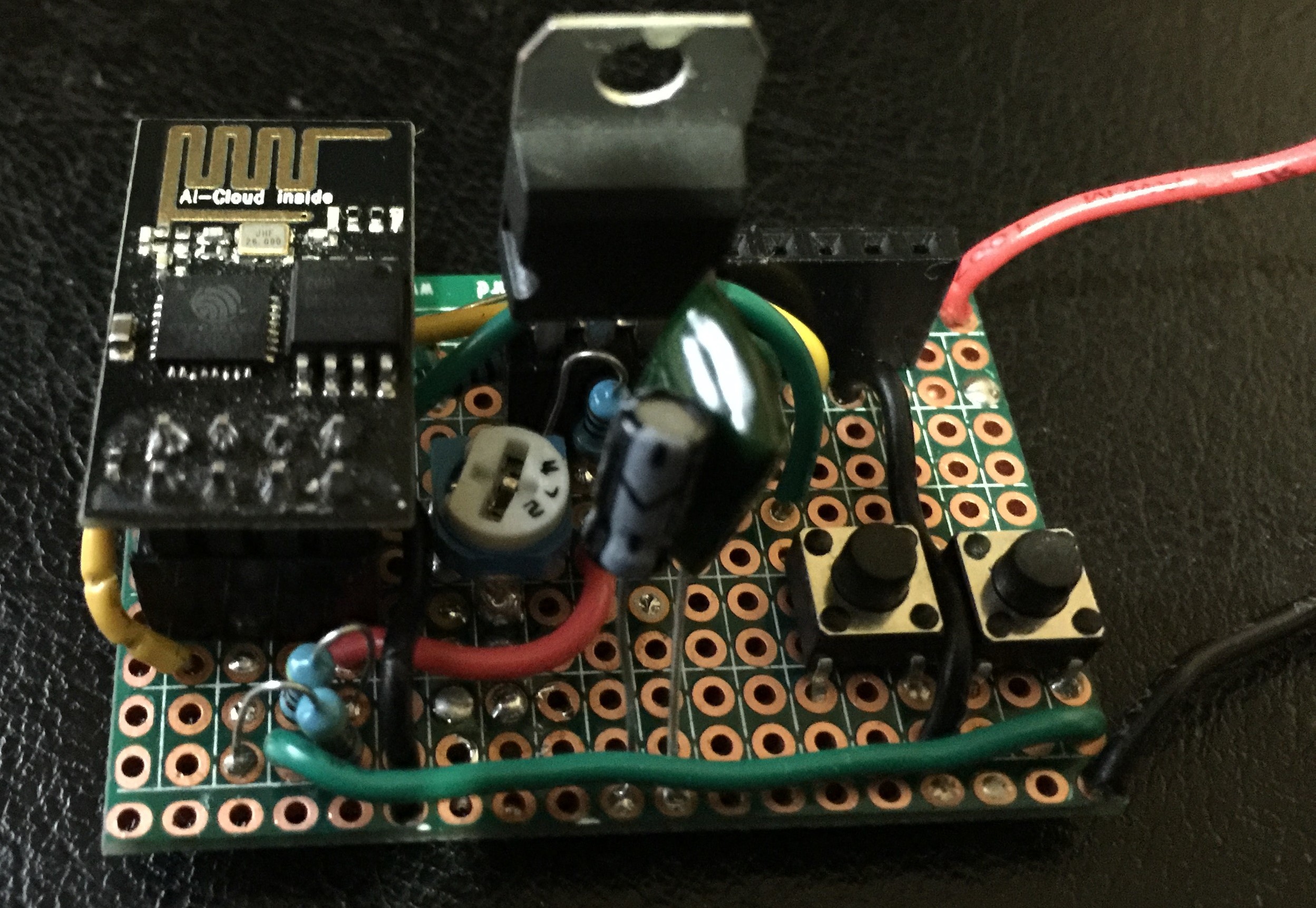
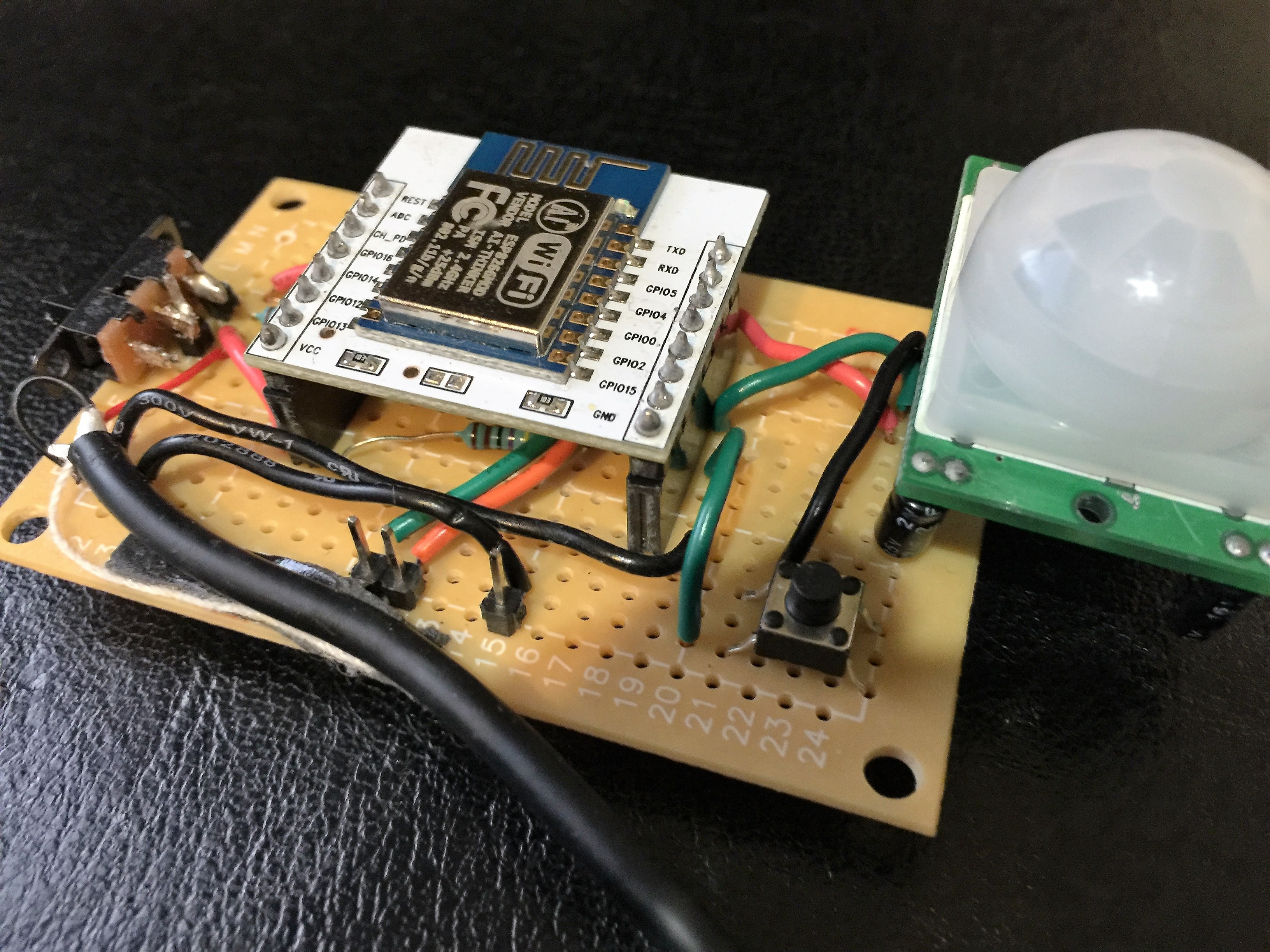
The connections between that one and the 16 pin module based board I'm currently using are almost identical:
The difference in component count comes down to the smaller module not including a voltage regulator. I ended up using a LM317 because that was what I happened to have in my parts drawer, but if I wanted to make a battery powered version of this I'd probably go with a switching regulator.
I wanted to use a USB wall wart and luckily the 3.3v Vcc the ESP8266 was low enough that the LM317's dropout voltage didn't come into play. The circuit is pretty simple, for the most part following this reference design (I used a 4.7K potentiometer instead of a 5K):
Both boards also have near identical pin connections:
| ESP8622 Pin | Connection on 8 Pin Board | Connection on 16 Pin Board |
| VCC | Vout of LM317 | Vout of a LDO 3.3V Voltage regulator built into the 16 pin module |
| CH_PD | 3.3v via 4.7k pullup | 3.3v via 4.7k pullup |
| RESET | 3.3v via 4.7k pullup (With a button that pulls it to ground to reset) | 3.3v via 4.7k pullup |
| TX | Serial Module RX | Serial Module RX |
| RX | Serial Module TX | Serial Module TX |
| GPIO0 | 3.3v via 4.7k pullup (With a button that pulls it to ground to enter programming mode on boot) | 3.3v via 4.7k pullup (With a button that pulls it to ground to enter programming mode on boot) |
| GPIO2 | 3.3v via 4.7k pullup | 3.3v via 4.7k pullup |
Note: The ESP8266 is really picky about connections. If the power supply doesn't keep up with the modules (and I found most USB-to-Serial converters couldn't), all sorts of weird things happen, from a chip that works but occasionally sends garbage over serial, to a dramatically overheated chip.
And a flaky power supply isn't the only thing that can cause severe overheating with them. The 8 pin module's board had a fault when I first set it up: the pullup resistor for GPIO0 was connected to the wrong hole on my protoboard, leaving GPIO0 floating during operation. Within 30 seconds the entire module was painfully hot, although even in normal operation they get warm to the touch.
Most of the increased component count on the 8 pin board is from the LM317 and the dedicated reset button (on the 16 pin board I didn't get around to adding a reset switch since the power switch is attached the the board).
The reason I switched from the 8pin module was GPIOs.
The original design was going to be fully motion activated. But I was worried about stray objects or pets triggering the detection, and I wanted an item that worked in multiple settings. Getting a calibration that would work "anywhere" probably wouldn't have been possible.
I thought about a few different solutions and went with the simplest: Adding a button to act as the trigger. The button could also serve double duty by allowing input without a secondary device. The problem with my solution was the module only has 2 GPIOs (and one interacts with the bootloader if it's not pulled up at boot).
There were actually some really interesting tricks on this page that could have let me use the 8 pin module, but to get developing quickly I didn't want to start waiting on parts (So far I've managed to only use stuff I have around), and I didn't want to give up any part of the UART which is always great for debugging.
I think once I have the design working correctly I'll probably migrate to the smaller board, since it takes up a lot less space in an enclosure, and I won't want to have the motion sensor attached directly to the board.
Discussions
Become a Hackaday.io Member
Create an account to leave a comment. Already have an account? Log In.