 Josh Kittle
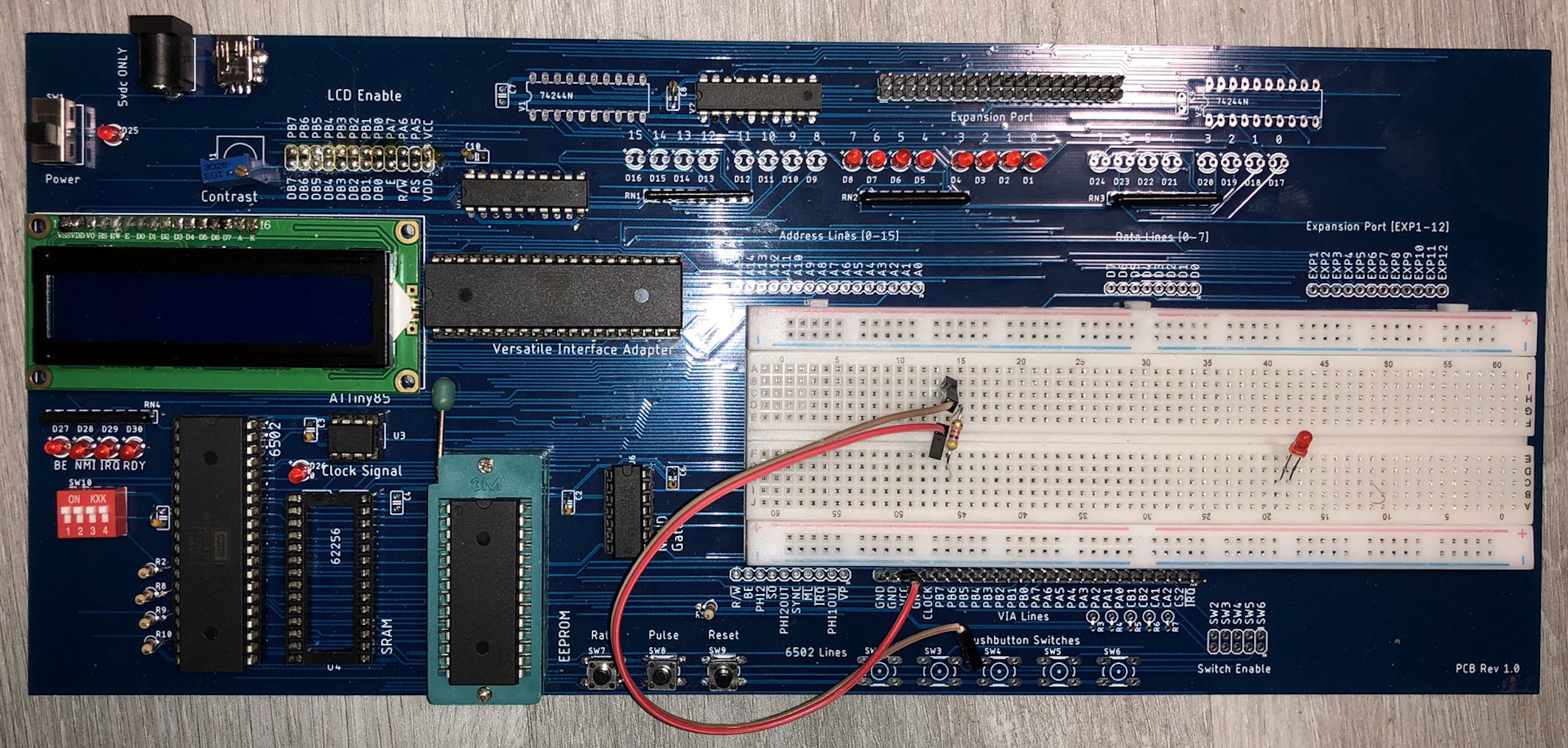
The Rev 4 PCB was really a turning point in the design. I decided to go with a blue soldermask, a design choice I'm going to stick with for this project. I really love the way it looks. The Rev 4 board is the first time I ever tested the EEPROM and LCD functionality (they work), and it really is coming into its own. I decided to lose the Arduino Mega footprint, and keep that function off-board. I'll talk more about that strategy later. Another really significant change is the use of octal buffer driver IC's to power the LEDs. I was pulling WAY too much current off the pins of the 6502, far in excess of the data sheet specs - I'm shocked I didn't smoke the thing. This approach significantly reduces the current draw on the address and data bus lines to a negligible amount. And one more thing, I opted to use resistor networks instead of single resistors to make assembly that much easier. Here's a layout of the Rev 4 PCB, the order went to the board house for these on 1/5/2020.
Even though the PCB shows 'Rev 1.0' on it, it's the 4th revision PCB. I just considered it the first 'release candidate'
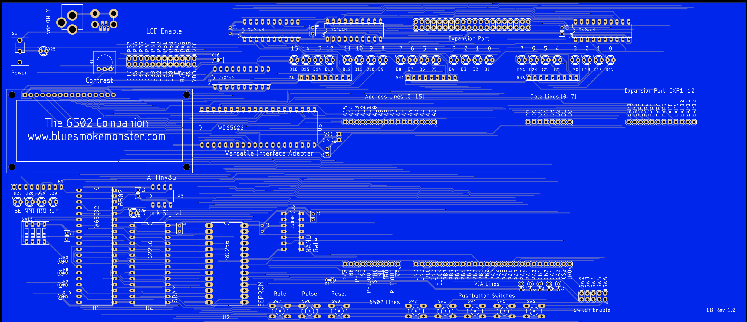
I rearranged the LEDs a little to break things up into nibbles, as well as reverse the order so the most significant / least significant digits made more sense to my head. All in all, this board worked very well. I finally settled on a good power switch footprint, and did a lot of testing with this revision. This would be the last fully through-hole revision. In the next board, we move into the realm of SMD. Shown here is the testing board for Rev 4.
Discussions
Become a Hackaday.io Member
Create an account to leave a comment. Already have an account? Log In.