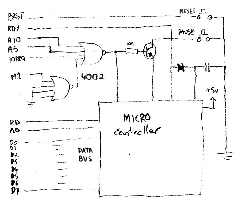
• Members of the Board

    darrenLindley01/21/2020 at 01:08 0 comments

    I have a reclaimed edge connector soldered onto a strip board that connects up to the expansion port of the 6128, I need a design for the rest of the board. When the z80 cpu is given an IN or OUT instruction it will bring the IOREQ control line LOW and M1 control line goes HIGH, and the READ or WRITE line will go LOW, anaddress will be put on the address bus, if its OUT command data will be put on the data bus and if it an IN it will receive data on the data bus. Timing of all this is the key to the card getting and sending data to the 6128, the Arduino Nano runs at 16MHz and the 6128 runs at 4Mhz so the fasted pulse the Arduino can produce is faster than what the 6128 can, handy. 

    Basically the 6128 will initiate communications with the card, when the apprpriate combination of lines go low on the expansion port the micro will trigger (hmmm, thats a keyword) and either  read from the data bus or change the data pins to outputs, put information on the data bus then once the data has been read by the 6128 the data lines need to become inputs again so they can be used by the 6128.

    I always find it good to see what other people have done similar to what I wish to do.  I had seen no projects exatly like this one but I did see this one by Ikonsgr (their user name on http://www.cpcwiki.eu/) hthis project uses a micro, a 4002 logic IC (of which I have one), is made for the 6128, the circuit board is provided, includes tools and setup instructions, there is also a few discussions on design on the CPCWiki forum. The circuit diagram is not provided so I thought Ide use the board design to extrapilate a circuit to see how it works. This is what I got;

    Well of course after I had finished the project and was putting this article together I find the original schematic.  The important thing to me at this point was the use of the 2 quad input NOR gates, these are used to detect the trigger conditions for this card to get going. The logic of the NOR gates is if any of the inputs are HIGH the output is LOW, so if the output of the gate with the M1 connected is opposite of the M1 line so this is low when M1 is high and if the A10, A5,and IOREQ are low this is the only time the output of the second gate is high. The A5 and A10 lines are used to address the card, the address 0xFBD is used for this card because this address has been alocated of serial, check out this IO Allocation page, bit 10 chooses the expansion port and bit 5 chooses the serial. So simply I can use this as an interrupt for the micro to trigger a read of the data lines, I dont need to worry about the rest of the circuit for now.

    I have to keep in mind this board needs to hook up to my new edge connector when it arrives so I added a row of pins that connect to the current edge connector, they also can be used for logic probing (if I didnt position these so low the case of the 6128 doesnt allow me access to the pins, carry on regardless).  I chose an Arduino Nano cos had one available, it fits on my strip board, it has enough pins and memory for the job and theyre cheap. I soldered a socket for the 4002, one for the Nano and layed out everything so Im not cramped on the board. I wired the output of the Nor gates to an interrupt pin and the data lines to the analog pins because ther are 8 and the digital pins I need other things.. this became a problem. The analog pins can be used as digital pins but there are 2 dedicated analog to digital pins which cannot be used as outputs so I can only use A0-A5, enought for a test, I left enough room on the board to rewire them later.

    I wrote a small program on the Nano to read the 6bits of data when it gets the interrupt and write it out to the serial port, and would you believe it, it worked, but not correctly, it would read something but it wasnt what I sent. I figured the Nano didnt read the data quick enough before the CPU released the data bus. I had read that the CPU can be paused by setting the...

    Read more »

  • Connection to the World

    darrenLindley01/20/2020 at 03:32 0 comments

    My floppy emulator has not yet arrived and I have some time to spare so I need to find a way to get software on and off this machine. I could use the cassette port but thats too easy so I need to access one of the ports. The printer port is only an output, the floppy is controlled by the floppy disk controller so would require a long winded deciphering process to use it, so that leaves the expansion port.

    My idea is to hook up a micro controller and access the computer  via a serial connection, or spi or  ic2 or give access to a sd card or lcd display. I looked around online for a information on the expansion port like this http://www.cpcwiki.eu/index.php/Connector:Expansion_port But how do you get data to it from the CPC, after a bit of research I found out you use the IN and OUT commands of basic or assembly. 

    During my research I came across a project that is similar to what I wanted, some one had resently built a serial port using a Pic micro controller and a few other components, heres the project : http://retroworkbench.blogspot.com/p/universal-serial-interface-for-amstrad.html .I had seen other projects using a bunch of ic or using an FPGA, but this used a micro, a  4002 logic IC, a transistor and a few other components, I had a 4002, game on!

    I needed an edge connector, they are not common anymore, the local Jaycar didnt stock them, the local computer store laughed at me ( I asked for a floppy cable with an edge connector, they claimed to have lots of cables), I found a 50pin edge connector on ebay but it turned out to be the wrong pitch, I eventually ordered one from the USA, Digikey. This would take some time to arrive so I looked for an alternative, what about a PCI slot connector from a motherboard,  Ive got a few boards that I harvest parts from but they are bigger and have a lot more pins, but lets give it a go.

    I cut the connector from the board with a rotory tool and checked it against the 6128 for size, it too long but I can cut it.  The connector has 124 pins, and soldered onto the board through holes, it cant be desoldered by me, I have to cut the borad so I have less solder joins per piece of board. The pins are interleaved and make diagonal rows of 4 pins, if I make diagonal cuts Ill have four pins per piece of board to desolder.  This worked but I couldnt desolder 4 pins per piece, I made a cut down the middle so I had 2 pins per piece then tried for one pin per piece by making another cut but the force of the spinning disk ripped the pins off.  I could still use the connector so I left it at 2 pins per piece and remove all the board, cut the connector and check contacts with the 6162 expansion port, all good.

  • Monitor Madness

    darrenLindley01/20/2020 at 02:19 0 comments

    I recieved the RGB-HDMI converter in the mail earlier than expected, but i dont have the SCART cable or the 6 pin plug. I figure I should be able to find some wire that I can poke into the video socket but the SCART connector requires small rectangular tabs. I could just solder wires ontot he back of the scart converter but thats a last resort, in the end I tried poking a bent wire I used for the 6 Pin socket into the SCART socket and it held, so that will do.

    Looking on the net there are various configurations for connecting the 6 wires from the computer to the 21 pin SCART connector, some used a capacitor, some used a 1.5v battery, some used a 5volt power source, the one I used just connected wires to pins.  First go it worked!  I could verify that the machine is alive, wha ha ha.

    http://www.cpcwiki.eu/forum/amstrad-cpc-hardware/rgb-scart-cable-done-myself-but/)

    The image I got was Black and White ( and 2 shades of grey) but I figured without the other power connections or components this is the best I can get for now, its enough to get other things happening,  I can try to get colour after the SCART cable and 6 Pin connector get here. I played around with the connectors and found I only need the ground (pin 5) and Luminance (pin 6) to get an image, but no other combination of connectors would get me any colour.

    (from http://www.cpcmania.com/Docs/Scart/Scart.htm)

    A Week Later..

    My 6Pin Din plug arrived and a little later the SCART cable, now I can finally get colour by adding the other connectors and components. I went through the different connection on the web and it seened that there was no other way to connect the Red, Green and Blue wires, there are several ground terminals on the scart connector but theres are all connected together on the converter so I only need to connect to one. So we have 2 pins left, pin 4 (SYNC)and pin 6(LUM) some diagrams have these pins going to the SCART pin 16 (Blanking Signal), pin 20 (Composite video in) or just not connected and 5volts to SCART pin 8 or pin 16 and 1.5volts to pin 16.

    Looking at the SCART pinout it seems that pin6 from CPC goes to pin 20 for B/W image, I know this cos it works, this pin is either Lum or Composite in.  If there is +1 - 3v on pin 16 the select is switched from from Composite video in to RGB and pin 20 becomes the sync source so pin 4 needs to be connected to this.

    For RGB mode:

    • SCART pin 16 1-3v, 
    • CPC pin4 goes to SCART pin 20, 
    • CPC pin6 not connected

    For B/W  mode

    • SCART pin 16 not connected
    • CPC pin 6 goes to SCART pin 20 ,
    • CPC pin4 not connected

    Unfortunately, on my SCART - HDMI converter pin16 is grounded so it can only do composite, GREAT!! I rechecked the product details and yes it only mentioned composite video. So I ordered on that does RGB.

    Side note: while writing this article I found a page where someone else who mentioned you only need 2 connections for a B/W image (cpc 464 have the same connector) I had not seen this till now.

    Simple CPC composite connection

    http://www.cpcwiki.eu/index.php/RGB_SVideo

    I had been wondering for a while if I could connect the pin6 and ground to a television using the video in but I dont have a TV in the work room so I didnt try, but the other day I realised I had a car DVD player with a remote screen which accepted a video in ( I had successfully connected this to a Raspberry pi) , maybe this could work. the screen requires a 9-12v power source which it came with and I hook a rca plug with aligator clips to the CPC and IT WORKED! Hmm portable screen. I could have done this ages ago,. Its only B/W and the clarity is a bit fuzzy but works. I could make a RGB to composite converter like the one below but the HDMI should give a better image, so I wait...

    http://www.cpcwiki.eu/index.php/RGB_SVideo

  • Mr Floppy

    darrenLindley01/19/2020 at 23:28 0 comments

    Unlike many other home computers of this era which used a 3.5" floppy disc drive, these machines used a 3" floppy disc (apparently they were cheaper), you cannot get these discs and I have only one.  I took the floppy drive out and discovered the drive belt had died,  I wont be using this drive but Ill will fix it because I can, so I order one of these from Spain.  

    Apparently it is possible to connect a 3.5" floppy drive to the machine using the external floppy port using an old floppy cable that has an edge connector. The internal drive has 26 pin connection, 3.5" drives have 34 pin connector, you can make a cable up but the external floppy drive port has 34 pins and is compatible with these drives. At the moment I have no way to get programs in and out of this machine, even when I replace the floppy drive I wont be able to connect it up to another machine, so if I can connect a 3.5" floppy I could get a usb converter and connect it up to another computer....but I still need to buy 3.5" floppys.  I realised this is silly.  

    There are USB floppy drives which connect via a floppy cable and store floppy images on usb sticks.  I thought I could just make one of these using a micro controller but Ill need a working floppy drive to reverse engineer the signals. I ordered a cheap Gotek USB Floppy and replace the floppy using the internal 6 pin connector instead of using the exteral 34 pin floppy port. Thats going to take some time to get here so I waited. 

    I bought a GoTek System SFRc922D USB Floppy Disk Emulator for about $32 AUD, It looked the same as the ones I had seen on various Amstrad floppy upgrade sites. Soon as I got it I took it apart to find it has a STM32F105 ARM Cortex-M3 CPU, I located all the jumpers to do the reprogramming with Flash Floppy so it will recognise the Amstrad DSK files.

    THe first thing I needed to do is make a cable to convert the 26pin internal floppy cable to the 34pin connector on the Gotek floppy emulator. I gave this a few goes using secondhand cables I had lying around but none worked so I decided to work out exactly what pins need to go to what.

    The pins on the underside of Gotek board are all earths, one of these should connect to one of the odd numbered (underside) pins of the internal FFD connector. The even numbered pins (upperside) match up on the higher number end but the lower 5 dont, the tenth pin on the 36pin connector goes to pin 2 on the 26 pin connector. To make sure Im making the correct connections I followed schematics of the 6128 and found that pin36 of the Gotek should connect to pin 2 of the exteral FFD edge connector terminal and pin15 of IC203 on the 6128 motherboard.  Pin8 on the Gotek board should connect to pin 28 of the exteral FFD edge connector terminal and pin4 of IC203 on the 6128 motherboard (see table below).

    Gotek pin       Int FFD pin     CPC motherboard
    34 --------------- 26                  External FFD port pin 2 / IC203 pin15
    32 --------------- 24
    30 --------------- 22
    28 --------------- 20
    26 --------------- 18
    24 --------------- 16
    22 --------------- 14
    20 --------------- 12
    18 ---------------- 10
    16 ---------------- 08
    14 ---------------- 06
    12 ---------------- 04
    10     nc   ,------ 02                   External FFD port pin 28 / IC203 pin4
    08 ---------"
    06     nc
    04     nc
    02     nc

    I made a circuit on a little piece of strip board just like the diagram above and underneath I soldered together all the pins of the 26pin connector and ran a wire to one of the underside pins of the 34pin connector. I made it a little too wide but it just fits.

    THE POWER CABLE NEED TO BE CONVERTED. The 5v and 12v lines are opposite on the Amstrad floppy compared to the standard...

    Read more »

  • Just getting the thing working

    darrenLindley01/19/2020 at 23:10 0 comments

    Looking at the Amstrad CPC 6128 there are 3 connections on the left side for audio, joy stick and cassette,on the back there is a printer port, expansion port, 5volt power, video in, power switch, volume control and external floppy drive port. There is also a cable hanging out the back which connects to to a dedicated monitor to provide 12volt power to the floppy drive, along with 2 other cables to provide 5volts and video. 

    I can connect 5volt supply, there is a tag underneath the machine which tells me it takes 1.7amps.  I dont need the 12v yet as I just want to check if the machine works. Turning it on I get the power led lit up and a click from the speaker. I dont have a monitor so the only way to check if its actually working is to press the DEL key and it should beep indicating there is no charactors to delete, this works, but as a further test I press a charactor key a few time then the DEL key the same amount of time before it beeps, this works.

    I needed a converter to allow me to connect a HDMI monitor to the 6128. The computer, like many of this era output an RGB signal to a CRT monitor. In Europe many video devices have a SCART connection (or had)  which allowed you to connect a RGB or composite video source to the device so it is possible that some of these monitors are still around or at least a scart cable.  I live in Australia, we didnt use SCART (although I have seen a cable somewhere) so I have to get a converter, a SCART cable and a 6 pin DIN plug. I ordered these on ebay over xmas so it was going to take awhile.