I recieved the RGB-HDMI converter in the mail earlier than expected, but i dont have the SCART cable or the 6 pin plug. I figure I should be able to find some wire that I can poke into the video socket but the SCART connector requires small rectangular tabs. I could just solder wires ontot he back of the scart converter but thats a last resort, in the end I tried poking a bent wire I used for the 6 Pin socket into the SCART socket and it held, so that will do.
Looking on the net there are various configurations for connecting the 6 wires from the computer to the 21 pin SCART connector, some used a capacitor, some used a 1.5v battery, some used a 5volt power source, the one I used just connected wires to pins. First go it worked! I could verify that the machine is alive, wha ha ha.
( http://www.cpcwiki.eu/forum/amstrad-cpc-hardware/rgb-scart-cable-done-myself-but/)
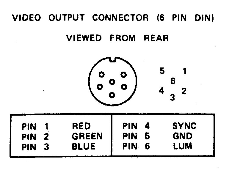
The image I got was Black and White ( and 2 shades of grey) but I figured without the other power connections or components this is the best I can get for now, its enough to get other things happening, I can try to get colour after the SCART cable and 6 Pin connector get here. I played around with the connectors and found I only need the ground (pin 5) and Luminance (pin 6) to get an image, but no other combination of connectors would get me any colour.
(from http://www.cpcmania.com/Docs/Scart/Scart.htm)
A Week Later..
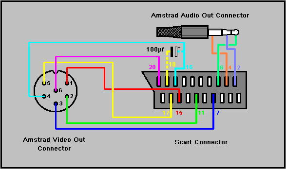
My 6Pin Din plug arrived and a little later the SCART cable, now I can finally get colour by adding the other connectors and components. I went through the different connection on the web and it seened that there was no other way to connect the Red, Green and Blue wires, there are several ground terminals on the scart connector but theres are all connected together on the converter so I only need to connect to one. So we have 2 pins left, pin 4 (SYNC)and pin 6(LUM) some diagrams have these pins going to the SCART pin 16 (Blanking Signal), pin 20 (Composite video in) or just not connected and 5volts to SCART pin 8 or pin 16 and 1.5volts to pin 16.
Looking at the SCART pinout it seems that pin6 from CPC goes to pin 20 for B/W image, I know this cos it works, this pin is either Lum or Composite in. If there is +1 - 3v on pin 16 the select is switched from from Composite video in to RGB and pin 20 becomes the sync source so pin 4 needs to be connected to this.
For RGB mode:
- SCART pin 16 1-3v,
- CPC pin4 goes to SCART pin 20,
- CPC pin6 not connected
For B/W mode
- SCART pin 16 not connected
- CPC pin 6 goes to SCART pin 20 ,
- CPC pin4 not connected
Unfortunately, on my SCART - HDMI converter pin16 is grounded so it can only do composite, GREAT!! I rechecked the product details and yes it only mentioned composite video. So I ordered on that does RGB.
Side note: while writing this article I found a page where someone else who mentioned you only need 2 connections for a B/W image (cpc 464 have the same connector) I had not seen this till now.

http://www.cpcwiki.eu/index.php/RGB_SVideo
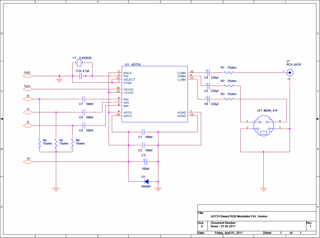
I had been wondering for a while if I could connect the pin6 and ground to a television using the video in but I dont have a TV in the work room so I didnt try, but the other day I realised I had a car DVD player with a remote screen which accepted a video in ( I had successfully connected this to a Raspberry pi) , maybe this could work. the screen requires a 9-12v power source which it came with and I hook a rca plug with aligator clips to the CPC and IT WORKED! Hmm portable screen. I could have done this ages ago,. Its only B/W and the clarity is a bit fuzzy but works. I could make a RGB to composite converter like the one below but the HDMI should give a better image, so I wait...
Discussions
Become a Hackaday.io Member
Create an account to leave a comment. Already have an account? Log In.