I have a reclaimed edge connector soldered onto a strip board that connects up to the expansion port of the 6128, I need a design for the rest of the board. When the z80 cpu is given an IN or OUT instruction it will bring the IOREQ control line LOW and M1 control line goes HIGH, and the READ or WRITE line will go LOW, anaddress will be put on the address bus, if its OUT command data will be put on the data bus and if it an IN it will receive data on the data bus. Timing of all this is the key to the card getting and sending data to the 6128, the Arduino Nano runs at 16MHz and the 6128 runs at 4Mhz so the fasted pulse the Arduino can produce is faster than what the 6128 can, handy.
Basically the 6128 will initiate communications with the card, when the apprpriate combination of lines go low on the expansion port the micro will trigger (hmmm, thats a keyword) and either read from the data bus or change the data pins to outputs, put information on the data bus then once the data has been read by the 6128 the data lines need to become inputs again so they can be used by the 6128.
I always find it good to see what other people have done similar to what I wish to do. I had seen no projects exatly like this one but I did see this one by Ikonsgr (their user name on http://www.cpcwiki.eu/) hthis project uses a micro, a 4002 logic IC (of which I have one), is made for the 6128, the circuit board is provided, includes tools and setup instructions, there is also a few discussions on design on the CPCWiki forum. The circuit diagram is not provided so I thought Ide use the board design to extrapilate a circuit to see how it works. This is what I got;
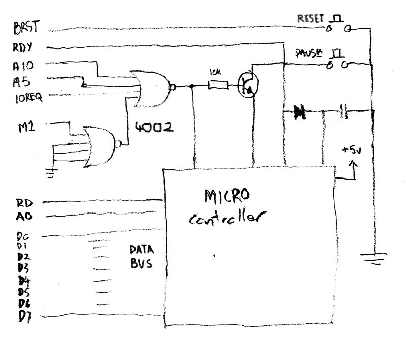
Well of course after I had finished the project and was putting this article together I find the original schematic. The important thing to me at this point was the use of the 2 quad input NOR gates, these are used to detect the trigger conditions for this card to get going. The logic of the NOR gates is if any of the inputs are HIGH the output is LOW, so if the output of the gate with the M1 connected is opposite of the M1 line so this is low when M1 is high and if the A10, A5,and IOREQ are low this is the only time the output of the second gate is high. The A5 and A10 lines are used to address the card, the address 0xFBD is used for this card because this address has been alocated of serial, check out this IO Allocation page, bit 10 chooses the expansion port and bit 5 chooses the serial. So simply I can use this as an interrupt for the micro to trigger a read of the data lines, I dont need to worry about the rest of the circuit for now.
I have to keep in mind this board needs to hook up to my new edge connector when it arrives so I added a row of pins that connect to the current edge connector, they also can be used for logic probing (if I didnt position these so low the case of the 6128 doesnt allow me access to the pins, carry on regardless). I chose an Arduino Nano cos had one available, it fits on my strip board, it has enough pins and memory for the job and theyre cheap. I soldered a socket for the 4002, one for the Nano and layed out everything so Im not cramped on the board. I wired the output of the Nor gates to an interrupt pin and the data lines to the analog pins because ther are 8 and the digital pins I need other things.. this became a problem. The analog pins can be used as digital pins but there are 2 dedicated analog to digital pins which cannot be used as outputs so I can only use A0-A5, enought for a test, I left enough room on the board to rewire them later.
I wrote a small program on the Nano to read the 6bits of data when it gets the interrupt and write it out to the serial port, and would you believe it, it worked, but not correctly, it would read something but it wasnt what I sent. I figured the Nano didnt read the data quick enough before the CPU released the data bus. I had read that the CPU can be paused by setting the RDY line (turning it on (HIGH)). this is why the transistor is used. When the Nor gates output a high it turns on the transistor and if the micro pin the emmitter is connected to is cleared to LOW, the RDY line will go LOW, halting the CPU when the interrupt is triggered giving the Nano enough time to read the data. The RDY can be sent High again by setting the pin connected to the emitter to High, the CPU will resume. I wired in the transister and low and behold.. it didnt work so I gave up cos it was all stupid...
I came back to it after a few days and got it to work, I cant recall the problem but I saw it quickly after being away from it for a few days. Getting the CPU to read was more difficult because you need to know when to turn the data lines back to inputs, if its done too soon the CPU wont have read the data, if too late, you tie up the data bus and currupt data sent across them. This problem had been mentioned by the developer of the io card I was following and they had used the doide and capacitor as a "sample and hold" so the micro could see the a change on the RDY line or something like that (I dont understand) I hooked up the logic analyser and worked out I just needed to watch the READ line, Ide have to write some assembly for this, I gave it a go and it worked.
I decided to use two of the digital ports for the D6 and D7 pins and Ide have to add the bits on these pins to the other data to get the 8bits I need, Its not ideal as it will add a few extra clocks to the timing but its good enough for now. Ikongr also used the A0 line to give the serial card 2 ports 0xFBD0 and FBD1, the 0 address is used to transfer data and the 1 address is used for control. I used this cos its a good idea, sending an IN 0xFBD1 will tell the cpu if ther are any bytes in the data buffer and using OUT 0xFBD1 you can set different configuration parameters on the card.
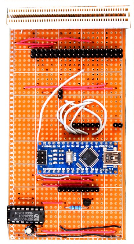
This is my board, adding the header pins made it a lot easier to connect a logic analyser. I had to use wire jumpers to order the data pins of the Nano to the edge connector. I also added a detachable jumper on the 5v line so I could remove the 5volts when a usb was connected.
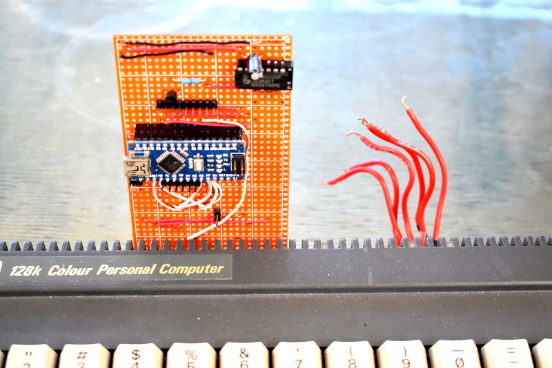
This is the card connected, as you can see the header I provided is useless, you can connect anything to it cos the 6128 case is in the way and its wired wrong to be able to connect a cable with an edge connector. I could heat teh solder and push the pins through, but I think they would be back to front...its just a prototype.
check out the red wires for the video out, Hack City
Discussions
Become a Hackaday.io Member
Create an account to leave a comment. Already have an account? Log In.