 Jarrett
I need some electromagnets.
A guy familiar to most of the community here named Carl Bugeja has designed coils drawn out in PCB traces to make a PCB motor. He shows off the design a lot here.
Included, naturally, are a set of gerbers which were worth ordering to play around with.
https://www.instagram.com/p/B479df4h5F9/
I tossed a magnet on there and was able make it jump around the coils using a small bench power supply. The resistance at each phase was about 12 ohm, the same value that Carl Bugeja measured. Each phase does go through three entire coils, however, so assume 4 ohms per coil.
The coil pattern is illustrated quite well with Carl's coloured gerber export:
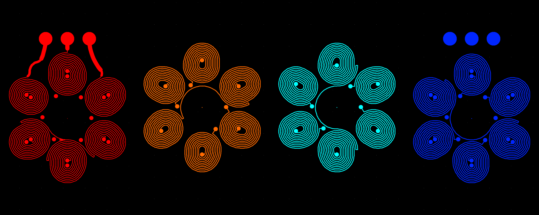
Application of the right hand rule shows that as current goes in a clockwise spiral direction (curl your right-hand fingers in that direction), your thumb will point in the direction of the magnetic field, out of the screen. Interestingly, the ordering of the coils on the layers isn't from top to bottom. Carl ordered it from layer 1(top)->layer 3->layer 2->layer 4(bottom). Probably to (very very slightly) increase the length of the current path and therefore the resistance of the coil.
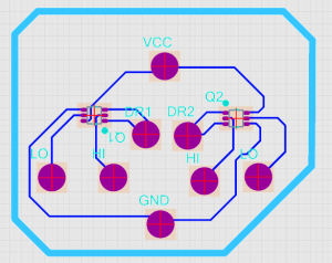
To drive a coil with any polarity we like, we need a standard H-bridge circuit. A future version might do some interesting stuff with that, so the fine control that an H-bridge provides is kinda cool. Generally an H-bridge consists of a couple matched pairs of transistors of opposite substrate. Poking around, there's a single chip MOSFET solution that looks suitable, the VT6M1.
So here's a quick PCB layout of how that would work:
But of course, just dropping that into a board is boring! We're going to make a pretty PCB, we might as well go all the way! I've spoken before about PCBModE. Using my tool to convert the above PCB into a compatible format, I pull it into PCBModE, cleaned it up, added some electromagnetic spirals, and a little bit of flair. There are solder pads to hook this PCB up to another PCB, containing all the brains.
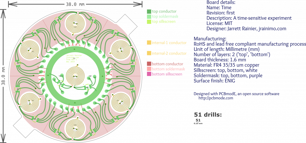
Figuring out a compact way to drive all those connections is somewhat challenging. With six coils around the perimeter and one in the centre, a "drive high" and "drive low" connection for each side, there are 28 signals, plus power and ground. All of those need to be transferred out to a "controller" PCB, so I added those green teardrop solder pads. The idea being that pins are to be soldered onto them, and then pushed into through-holes on the controller PCB.
Discussions
Become a Hackaday.io Member
Create an account to leave a comment. Already have an account? Log In.