 Johan von Konow
Development
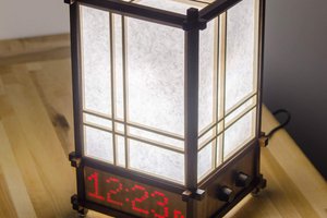
I started with the segment design. Personally, I think that most 7 segment fonts have too sharp appearance (curves and corners). I spent way too many hours in redesigning the digits (definitely overkill, but once you are down the rabbit hole...). In the end, I think I got a striking rounded, friendly design that is easy to read, has a retro look without looking dated.
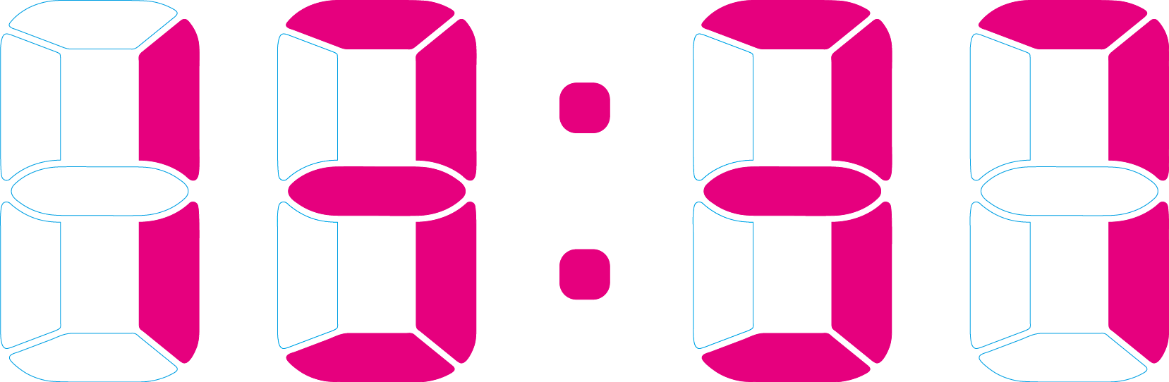
I didn’t use italic digits because I wanted the clock to be calm, plain and neutral (italic segments tend to add speed and futuristic look)
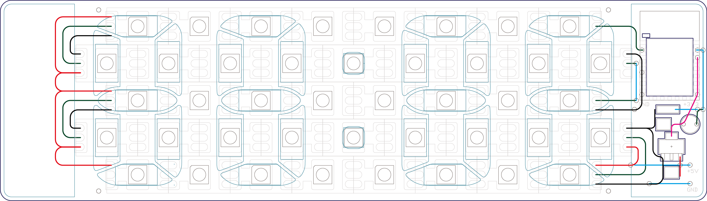
By using an ESP8266 and ws2812 LEDs the electronic design was dead simple. An LDR and a resistor configured as a voltage divider allows light measurement and dynamical light intensity. I also added a 3.3V LDO and two decoupling capacitors. It is truly a minimalistic design using only two I/Os on the ESP. Power, Wi-Fi and light in, time out...
My first idea was to design a custom PCB with LEDs for each segment. I quickly realized that by adopting the spacing between the digits to a fixed distance I could use a strand of addressable LED strip, replacing the need for a custom PCB. This means that 12 LEDs will not be used, but it’s a small price to pay for the gained simplicity. By choosing different LED strip densities (number of LEDs/m) I could adjust the size of the clock. I settled with the standard 60led/m which is easy to get and gives a medium size clock (190x54x4mm)
By using my 3DPCB idea I integrated the components and wires in the opaque light blocking structure. I separated the electronics from the segments, allowing me to tune the design if needed. The light blocking structure was printed in white PLA (which is far from opaque), but still limits light leakage at the same time it allows background LDR measurement without visible components (thru the white front).
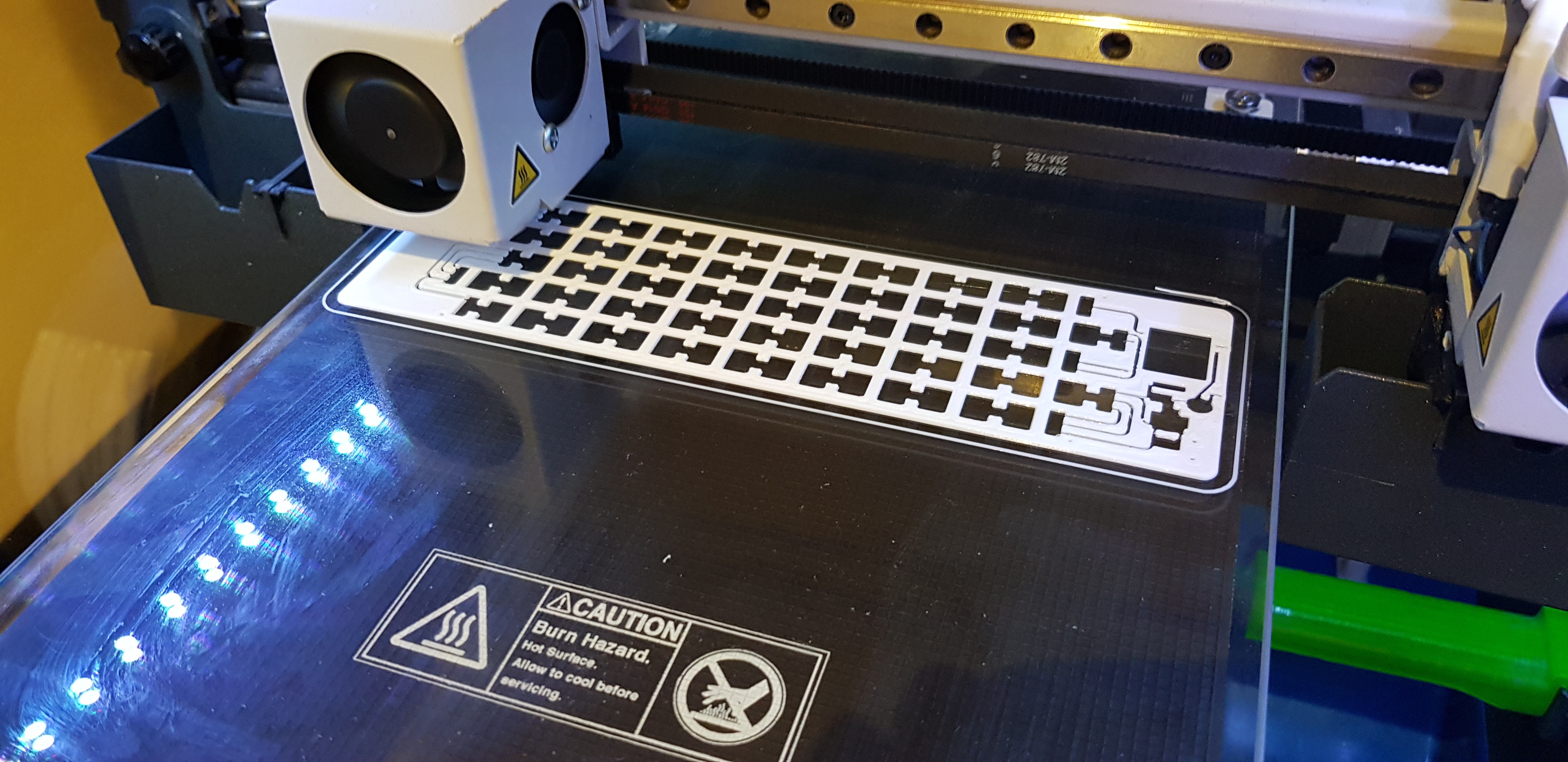
The segments are printed in transparent PLA which results in a light diffusing plastic that works really great.
Read more about the program, assembly and necessary files on my blog.

 The Big One
 sjm4306
 bram
bram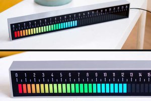
 Maakbaas
I was wondering why the LEDs were set up in this odd pattern, and at first, it looked like there was a fair bit of excess...
But actually, reusing WS2812 LED strips like that is a great move!
Reduces or completely removes the need for a custom PCB provided you can get a controller, which makes this a lot more accessible to anyone who is looking for a fun project.
Very well done!