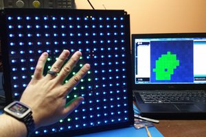
Here are a few videos of the finished hack
Hacking the Crayola POV Dome Thing
I found a Crayola Digital Light Designer in a bargain bin and thought "What a Hack TREASURE!!!"
I found a Crayola Digital Light Designer in a bargain bin and thought "What a Hack TREASURE!!!"
To make the experience fit your profile, pick a username and tell us what interests you.
We found and based on your interests.
Here are a few videos of the finished hack
sch01.gifReverse engineered circuit for the motor enableGraphics Interchange Format - 285.62 kB - 03/14/2020 at 23:56 |
|
|
povNano05.zipMy uncommented hacked code for the adventurous, it displays a flapping birdZip Archive - 3.62 kB - 01/29/2020 at 21:48 |
|
|
povSignals.jpgSignal from the controller board to the Led barJPEG Image - 38.06 kB - 01/22/2020 at 02:11 |
|
|
ledConnections.jpgCable to the LED barJPEG Image - 56.84 kB - 01/22/2020 at 02:10 |
|
|
Now all is running well, a bit shakey and noisey but the graphics look good, time to create some proper images instead of test patterns. I looked online for iconic images using only primary colour, found Superman 'S' symbol, I also grabbed the Hack-a-day symbol. In Gimp I reduced the images down to the 8 colours I can display and reduced the height to 32 pixels, after much editing I had versions I was happy with. Gimp will export images as 'C source code' and because this is a text file I can edit the values in a text editor using search and replace. I spent a few hours doing this just to realise that I was creating array declarations of pixel ROWS, what I need was array declarations of COLUMNS, grrrr. A few hours later I had it working and it look awesome!!
Not happy with displaying one image I made some small modification so it would do a slide show, worked perfectly, actually better than I expected. The change from one image to the next was instant so I changed the display pereiod of each to 100 milliseconds and I was animating, lets fo an animation. I found a simple anumation of a flapping bird silouette, converted it to 8 images and presto, animation, it looks really good!.
What I need now is a frame buffer to represent the display in memory so the images do not have to be constantly calculate on every spin. Up till now I convert each line to the POV data structure and store them in different variables then draw them one by one. All I need to do is store the lines into an array during the initialisation process then draw each element of the array on every revolution of the spinner. I created an array of POV structs for 200 elemnts, gave it a go and it didnt work. I cant be using up all the memory, I still have 28k left to use! I changed somethings around and it still didnt work, and weird things were starting to happen. The Arduino program wasnt recognising my board, I had to rest the board and send the code before it completely reset.
Thats when something in my head said, is that 28ks of ROM or RAM. Check out the datasheet and I only have 2k of RAM to play with, this is enough to display about 50 columns. I looked and looked to get around this but you can only use flash to store variables that wont change, no good for this purpose. I wanted to setup some tests without the motor runnung and send back information using the Serial port but now I think my frame buffer has run into my boot loader cos the Serial wasnt working. This combined with the board not being recognised without resetting the board made it so frustrating I decided to abandon this board and use an Arduino Nano (under $10.00 online).
I also decide to make a platform for my board on the spinner and to add weight to counter balance the board. I used an old plastic membership card and glued it so the board would sit horizontally reducing wind resistance. A few days later I had the new board in and running great.
I though of adding external RAM, but I dont really want to add extra circuitry (Ive already added a resister). In the end I decided to try doing everything on the fly, change the image data to POV struct as needed, maybe this will give me the ability to draw the 200 columns I want. I tried that but the extra processing increases the time it takes to display a line on the screen which increaed the length of a pixel (ugly), now I can only get ~50 columns in one revolution.
So for now Ill go back to the 50 column frame buffer and use Flash memory to store my image arrays, which is fine cos you can only see a quarter of the screen properly anyway. Maybe using the Flash memory and condensing my code I can get aslightly bigger buffer.
The thing to do now was get the synchronising working. The detector has no markings, only two leads, and is polorised (positive is marked on the board). I couldnt find a similar image on google, but has to be a photodiode or phototransister, not knowing which means I didnt have a circuit to try. I connected it up to the multimeter to see what it does, it give high resistance by default then low resistance when lit. I decided to connect it to a MCU pin and ground and see if that worked, at low speed it did intermittedly and at high speed it didnt.
The best way to use this would be to get it to produce an interrupt which would start the image drawing, so I set up the micro to detect a pin change, this didnt work at all. Did I have the interrupt set up correctly, was the Leostick exactly the same as a Leonardo, were interrupts the same? Having everything set on a spinning board was making it difficult to test things out, I had no debugging, the motor would run as soon as I turned on the power, I needed to power the device because it drove the timing ir led. There was a momentery kill switch for the motor as part of the original device so I could use this to test the led trigger but still it was frustrating.
I was hoping to get this running without adding circuitry but now I was thinking transisters as a switch for the interrupt. I gave it a go and it didnt work, maybe I needed a second transister so one was an amplifier and the second was a switch, this didnt work. Now I was thinking Ill have to set up biasing using resisters, I gave it a go but it didnt work.
Now I started thinking about the original board, this had some transistors, capacitors and resistors, maybe they were all part of the triggering circuit. I got the multi meter out and followed the traces which were hard to see because everything was painted black, after poking around for awhile I wasnt getting anywhere, the detector did connect up to this circuit but visualising it was difficult. I though if I scrap away the paint I could see where everything goes and draw the circuit, so that I did. The circuit had a lot of filtering but essentually the detector connected to one transister which connected to another and there were a few lines which went to the controller. At this stage I thought this circuit is designed to do what I need done, its already miniturised I could cut it off and use it. I did that and it didnt work.
My last attempt was to use a voltage comparitor, which doidnt work.
The problem seemed to be that the interrupt pin was providing a +5v and stuffing up every circuit Ide build, but the detector needed power to work and my electronics theory wasnt good enough to work out what to do. As a last resort I thought I could use a Halls effect device and a magnet, atleast I would know what Im dealing with, but the led and detecor should work (it did originally).
Eventually I thought what if I just use an analog pin, the detector worked with the multimeter. I set up a test using a variable resistor between the +5v and an analog pin which had the positive end of the detector connected, and the negative end of the detector to ground. I wrote a program to turn on the pin 13 led if a pulse was detected then varied the resistor while moving the detector over the led, it worked. I subsituted a fixed resistor for the variable one, soldered everything to the Leostick and it all worked. This method isnt acurate, the image wil flick back and forth a bit, but it works and Im relieved
First I coded a shift_out function which would turn a byte into a series of clocked pulses. Then I work on a method to mask off and encode the red,green and blue values from an array of integers representing colours so I can create bitmaps for each colour component. Having done this allowed me to describe a line pattern using abbreviated colour names re,ye,gr,cy,bl,pu,bk,wh making easier to create images.
An image array is then converted into a structure to store the address, value and frame of each led which is sent to the the shiftout function which creates the line pulses for the led display.At this point I could see my patterns being displayed but because they werent synchonised I had to play around with array sizes so I could get images slowly floating in different directions this also showed me ~200 columns could be displayed in one revolution.
I thought it best to first get things working without the synchronisation and worry about that later.
I desoldered the header sockets (by destroying them) so I could solder leads directly to the board to minimise weight. The first attempt didnt work, the micro kept resetting. Because the power is supplied via wipers on the slip rings, maybe the powersupply isnt clean enough so I added a capacitor to provide a constant supply, worked great.
Now the MCU was attached to the original power supply I had to disconnect the power to reprogram the MCU via usb, this was going to be a pain so used a double pole power switch to totally isolate the MCU when the power is switched off.
I thought the best way of going about running the display is to provide my own micro to control the leds, at this stage Im not too interested in using the light detectors (they seem to be photodiodes), but the synchonising detector is provided on this board so Ill use it for this reason and to balance the spinner.
For simplicity and size, I chose to use a Leostick (Freetronics version of the Arduino Leonardo) for my MCU. I cant use the same mount for because the motor shaft needs to contact the protective dome so the board would need a hole through the middle. After much pondering I decided to mount the micro by attaching it on the motor shaft using cable ties, it shouldnt upset the balance too much.
Writing the code
The original board ran at 24Mhz, the MCU Im using runs at 8MHz so timing may be critcal to get it working correctly so Ill avoid using the Arduino syntax for efficiency. The idea was to get the same led sequence running as the original using my own power supply and not being attached to the spinner, then get it running on the spinner.
I connected the boards up to 5v but the boards wouldnt work, I theorised there is a synchronising LED and detector that triggers the writing of the LEDs, without the detector picking up a pulsing light the LEDS dont light up. I got out the Arduino and wrote a program which would pulse an IR LED at a rate I can vary via the serial port and taped this LED to the detector. It worked, the LED bar flickers and if I moved the bar quickly I could see an image (theres an image of it in the gallery). Once I had the boards running I connected hooked up my logic analyser to the ribbon cable connected to the led board (via a header I solder to the board), fortunatley the positive and ground pijns were labeled.
I was expecting a similar protocol to the a shift register driven led matrix display I had built previously, so it took me quite awhile to make sense of the protocol. I was a bit confused for awhile because there didnt seem to be a regular clock, but it turned out the samples of the clock line werent perfectly regular which made it hard to recognise. Once I made out the clock I could see the dataline and two enable lines, it seemed to bean SPI protocol, I wasnt 100% sure so decided to replicate the pulses in code, at least to get it all going then may be implement SPI later.
The display runs a start up with a sequence of leds running up, down and back up the display, this gaves me something to relate the logic data to. Before the sequence starts an initialising data is sent to the display, I dont understand what it does but all I have to do is send the display the same sequence so dont need to understand it (would be nbice to though).
Data is sent through the data line, a display enable line enables the display, 2 frame lines are used to address the line of leds, the first frame line enables the first 16 leds and the second frame enables the last 16. 12x8 bits of data are used to display one line of leds, these can be broken up into bitmaps for each colour component of a group of 8 leds. 8bit for red component of first 8, 8bits for green, 8bits for blue, 8bits for red of next 8 leds and so on. The data is prefixed with 8bits of addressing data 0x80,0x81,0x82,0xC0,0xC1,0xC2, the same is used for the last 8 leds.
The first problem, the screws had 3 grooves in the head and I had no screw drivers for this, I had to use a small flat head. The base came off first, containing a circuit board with 3 leads connected to some slip rings providing connections to the spinner. Removing the top dome gave me my first look at the spinner, comprising of a frame to hold a top horizontal pcd connecting to two other pcds at each end, one holds 32 RGB Leds and connects via a 8 wire ribbon cable and the other holds 17 light detectors connected via a 18 wire ribbon cable. The top pcd contains some kind of integrated circuit under a blob of epoxy, there is a labelled USB pinout on the the board, three leads comming from the slip rings, the +5v line is labeled.
The next task is to remove the spinner so I can use a logic analyser to look at the signals going to the leds. There's no obvoius way of removing the spinner, but I could see 3 screws holding the motor cover on, maybe this may release the spinner. It didnt, I fiddled for a bit, finally giving it a bit of a rip and pulled it away from the main housing.
I had removed the spinner from the housing but to get it back on I need to feed the slip rings through the slip ring wipers, the motor housing still attached to the spinner made this very difficult. When I eventually got the spinner back on, the device didnt work. I removed it again, there must be a way to remove the spinner from the slip rings inorder to reseat the slip rings, fit the motor cover and then connect the spinner. After much banging and pushing I managed to get the spinner off, assemble the device and got it working again. This is hard to imagine unless you have one, the point Im trying to get across is taking something apart with the aim of putting back together and have it work can be frustrating but one of the main arts of hacking.
I disconnected the one of the wires to the motor so I could check which of the other 2 unknown wires was the ground, then proceeded to disconnect the boards from the spinner. The main pcb is held in place with two screws and both the led and the light detector boards unclip from the spinner.
During my usual rummage through the clearance shelfs in a local department store I found a kids toy, The Cryola Digital Light Designer. It looked like some kind of POV (persistance of vision) display, but was only $15 (AU) and was a kids toy.
I bought it, took it haome and after finding a power adaptor I got it working. Basically it was a drawing device, it came with an LED wand used to draw to the screen of 32 rotating leds. It had many different activities to choose from ranging from creating drawing and animations to racing games, but it was noisey and limiting.
Ive always wanted to build a POV display but didnt really have enough reasons for such a project to get to the top of the todo list, such a project required building a balanced spinning harness what could supply power to some circuitry and a good reason to spend the time and effort. Finding this thing gives me the head start I need and for $15, its not a huge investment.
The main thing I want this to do is to be able to display images Ive created on a computer and up loaded to it, even turn it into a computer display.
Create an account to leave a comment. Already have an account? Log In.
THe Flash.h file contains code so I could store the image data in a FLASH_TABLE, I did this to use the flash memory, theres a discussion on it here https://arduino.stackexchange.com/questions/611/what-are-the-flash-array-flash-table-macros-in-this-code
The Arduino Nano sketch contains a reference to a file library called "Flash.h", but I see no library attached to the source code. Does anyone know what Arduino IDE version was used with this code or where I can get a copy of the "Flash.h" file needed to compile? I tried using some flash related libraries downloaded with my current IDE version 1.8.0, but none seem to be compatible.
The origiinal write up was published on Hackaday in 2014 heres the article https://hackaday.com/2014/11/24/hacking-the-crayola-digital-light-designer/#more-139484 , The articles I wrote start at http://sureoakdigital.com/articles/blog/2014/08/hacking-the-crayola-digital-light-designer-pt1/ but that site doesnt exist and I didnt save the wordpress databases or I did but cant find them. I managed to find most of the original articles on the wayback machine as suggested by fdufnews, I compared these to the notes I published recently and they are mostly the same, just spruced up a bit with a bit of comedy added, I couldnt find the last article though. If you want to see them enter the address for the first article into the wayback machine and follow the links to the next article.
So I have a couple of these, for exactly the same reason. Can you elaborate on the wiring? It looks to me that there are two GND and two VCC lines on the LED board, and the 5 pins in the middle are the data lines. I think I've gleaned most of it from your demo code - it looks like the pins are: VCC, VCC, Frame0, Data, Clock, Display Enable, Frame1, GND, GND.
I'm not sure which pin on the sensor board is the indexing LED, and I don't see the Motor pin being used, either.
I plan on using an ESP32 board for this, so I can control it via wifi. (that part's up in the air, heh.)
I cant remember any specifics beyond what I ve written as I did this project awhile ago. I do have the board some where but I cant think where. I dont believe there is a motor pin and the sensor may have been on the other board. If I find more info Ill let you know.
I found the board
Terminal Nano
1 Gnd
2 Gnd
3 D9 (PB1) fr1Port
4 D8 (PB0) disPort
5 D7 (PB7) clkPort
6 D6 (PB6) dtaPort
7 D5 (PB5) fr0Port
8 VCC
9 VCC
The motor has an enable line but I dont think I used it, in the code it says PB4 but I dont think anything was connected because there is no need for the code to shut down the motor. I reverse engineered the circuit for the motor enable, Ill upload it.
the sensor id on the othe board, if you are looking at the terminals with the board turned so the terminals are at the top of the board the top right terminal is GND and the bottom right terminal is the sync detector.
I found some more notes, Ive added them to the logs, theres some stuff about syncronisation, hope this helps.
This project is from 2014, I had published it as an article on one of my Wordpress sites which has since been retired, so for prosperity I rewrote it on Hackaday.io. The "Dome Thing" was a noisey thing I had lying around till I down scaled to move house, Ive kept the electronics but the POV is no more. I compiled this write up from my notes, the original article had more detail, I thought I saved the wordpress database for it but couldnt find it in my archives, Ill have another look soon. Thanks for your interest.
Maybe you can retrieve it on the wayback machine https://archive.org/
My old "Lite-Brite" from the 60s looks a little dull by comparison.
I think I also missed all the cool toys. Great job @darrenLindley making this one a lot more awesome with the added Arduino. Are there more details on the process?
Become a member to follow this project and never miss any updates
By using our website and services, you expressly agree to the placement of our performance, functionality, and advertising cookies. Learn More

 Andrew Woodbridge
 caBattista

 engunneer
I added the Flash.h from the github. Thank you. Arduino IDE version 1.8.10 complained when compiling, but older versions compiled with just a warning about low memory. I will try running the final program on my Nano tomorrow.