 Yann Guidon / YGDES
The last time I designed a test rig, it had a crude but cute 4-bits R/2R ladder with a 2N2219 (metal can with hfe=100) for current amplification. It was nice enough to inject increasing amount of current into the DUT's Vcc input in 17 steps (0..15 and full-on with a 5th bit, so yeah, 5 bits DAC).
For this system, I need something more accurate and more resolution : ideally sub-mA resolution (100µA resolution but not necessarily accuracy since accuracy will be relative and correlated between all the measurement). Maximum required current in 100mA so a 1024 steps generator works to measure significant data.
But this is not as easy as it seems, each chosen topology has their own inconvenients.
The original R/2R-Ladder version is not precise or accurate, but this was not the purpose, I just wanted to inject "some current". It was actually not that inaccurate, BTW, but the BJT can drift with temperature and power supply voltage... Furthermore, the bipolar transistor's threshold voltage of approx. 0.7V means that the very first steps are ineffective.
I've used a trick though : the NPN transistor is mounted "high side" so the initial current is actually the 1/100th base current coming from the R/2R ladder. Short circuits are very easy to spot early withouth any damage. The ladder is powered from a 74HCT273 (octal latch with reset) tied to 5V so full-scale will provide 5V on the BJT's base, and the DUT's voltage can be measured (a high-side resistor heps infer the actual current).
Maximum supplied voltage is around 5-0.7=4.2V (depending on Rsense drop), full 5V is then provided with a P-MOSFET to short all that when we're sure the circuit's ramp-up curve is clean. It's pretty neat and safe to detect shorts on the power rails but not suitable for coil characterization.
In the current case, I need accuracy and resolution. Hence, some kind of feedback. Also, from past experiences, I must reduce the count of reference voltages to the least possible. A single 4.096V reference should be enough, so all the drifts are proportional and cancel each others. After all, I want to group relays in "similar" bins, I don't have an "absolute" requirement, they should be as close to each other as possible.
The same device (ADC) must measure the coil voltage and the current. Using Ohm's law, we can make a simple string, for example with a sense resistor on the lower side, and the DUT just above.
        Rsense      coil       Transistor
0V |----\/\/\/----o  DUT  o--------T-----| 5V
          10      ^  39   ^
                 V1       V2
The coil voltage is relative but not critical, it can be obtained from V2-V1. V1 gives an absolute reading of the current .This simplifies the grounding and there are only 2 voltages to measure. This topology is easy on the DAC because these nodes are low impendance, which should reduce the inaccuracies created by high-impedance transmission. A 12-bits ADC with 4.096V reference will have a 1mV bit-step, or 100uA step. Very nice.
The Rsense is easy to calculate: given maximum 100mA and 1V drop (leaving 4V headroom for the DUT+Transistor), Rsense=1V/0.1A=10 Ohms.
Do I have 0.1% 10 Ohms resistors in stock ? I found 1/2W 10 Ohms resistors that should fit but I can't validate the absolute value and accuracy with my lousy tools. Power would not exceed 1V×0.1A=0.1W so 1/2W provides a comfortable margin. Current-induced temperature drift will be low thanks to the ceramic package.
(Just in case, I ordered some 1% parts)
OK I got 1% 10 Ohms resistors. How can I get a better precision ? A series-parallel connection can even out the little differences. It takes 4 resistors, but can also sustain 4× more power.
|----\/\/\/-------\/\/\/---|
|                          |
|----\/\/\/-------\/\/\/---|
Well, that was the easy part. The hard part is how the heck am I going to feed the current into this R-DUT chain ?
A high-side transistor is required. I'm not sure what kind, yet, though, but more important is how to control it.
I don't trust the PWM output of the Pi for a cheap/crude DAC, nor the previous R/2R ladder. Ideally, I'd have a 8-bits, parallel-input DAC, to provide feed 0 and 64mA in the coil. 64mA/256=0.25mA resolution, it's still good enough since the worrying deviations are in the order of 5 to 10mA.
Rumaging through my archives, I found a couple of samples (Thank you Maxim!) of parallel-input, latching R/2R DACs:
(I got plenty of other DACs to play with but I wanted DIP and other low-tech features)
Fed with the common 4.096V reference, it is possible to create 256 voltage steps. An opAmp (rail-to-rail, please) will then compare this control voltage with the sense resistor's drop (a ÷6.4 divider network is necessary though). The error will drive the pass transistor, to create a classic voltage-controlled current generator.
Note: a 2.56V reference creates a 1:4 ratio, easier to create with 5 precision resistors.
Souces of relative errors will be
- the curent-sense resistor
- the offset from the opamp
- the 1:4 resistor divider
- any spurious resistance in the ADC
For the ADC, I elected to use a Burr-Brown ADS7825P. Thank you TI.
This is an old but fast (40Ksps) bipolar 16-bits successive approximation converter with 4 inputs and serial and parallel output. Input range is -10V to +10V with an internal 2.5V reference. I've used it in my previous test system so I can reuse some code.
Wait, 2.5V is not far from 2.56V, and the datasheet shows that the internal reference can be "pulled" a bit. The block diagram shows that a resistor connects the internal ref to the internal buffer so it can be overridden.
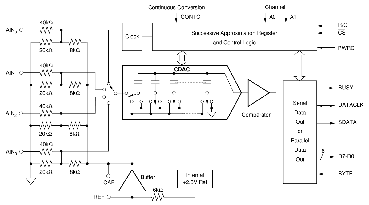
From the PDF:
External Reference Voltage Range for Specified Linearity: 2.3V to 27V
So let's use the same 2.56V external (buffered) reference for the ADC and DAC ! There is no harm because the input voltages will not reach 10V anyway and the conversion from binary to volt will be much easier.
This ADC has 4 inputs that can enhance the precision. Assuming the ADC actually outputs 2.56V precisely, we must read (2^16/8=) 0x2000 if we connect the REF to one analog input pin (plus or minus a few LSB values because of whatever non-linearities). Similarly, we can use the remaining analog input to check the DAC's output. The system becomes self-calibrating !
From the PDF (p15):
CALIBRATION
The ADS7825 has no internal provision for correcting the individual bipolar zero error or full-scale error for each individual channel. Instead, the bipolar zero error of each channel is guaranteed to be below a level which is quite small for a 16-bit converter with a ±10V input range (slightly more than ±32 LSBs). In addition, the channel errors should match each other to within 16 LSBs.
For the full-scale error, the circuit of Figure 9 can be used. This will allow the reference to be adjusted such that the full-scale error for any single channel can be set to zero. Again, the close matching of the channels will ensure that the full-scale errors on the other channels will be small.
Again, my goal is to sort relays and bin them in relative characteristics, not precisely absolute, so it's fine.
Voltage reading:
The 2.56V reference lets the ADS7825 sense between 10.96V and -10.96V (minus a meaningless LSB).
The range of 2.56V is quadrupled by the 1:4 input resistors, then doubled again for the negative range, the 0x0-0xFFFF range sets the 2.56V value at 0x2000 (8192). Each LSB is 312.5µV (10mV/32), instead of a more complex decimal number... The datasheet claims an accuracy of 32LSB, or about +/-4 bits, or 5mV, which is reasonable for this application.
The only problem is that I don't find a 2.56V reference IC. I only see 2.5V references :-(
I have to find a trick though. An ugly one comes to mind: reuse the 2.5V internal reference and "pull" it by 60mV toward the 4.096V reference. The internal 6K bufer resistor is probably in the 10% precision range so a certain amount of "fine tuning" is necessary with a multi-turn pot.
What is the value of the "pulling" resistor ? First, let's evaluate the current that is required to "pull" the 2.5V reference output to 2.56V: deltaV=2.56-2.5=0.06V. R=6K, I=0.06/6000=10µA.
U=4.096-2.56=1.536V, R=U/I=153600 Ohms
The calibration procedure would adjust the trimpot until the reading is 0x2000. Adjustment for 0V offset is not yet certain because of ground noise but a sliding switch could do the trick...
The other solution is to simply recalibrate on the fly, during each measurement cycle: read the 4.096V ref input along with the others and apply a rule-of-3 to get the actual value. But then there is no 2.56V input to the DAC to generate proper voltage steps.
The ADC measurements suffer from unknown offset but this offset might be mitigated by another trick. It's possible to measure/sample the voltage at the mid-point of the current sense resistor. Given the fixed point at 4.096V, an unknown current but a known relationship between the resistors, it is possible to calculate the 0V offset.
|----\/\/\/--*-----\/\/\/---|
|      10    |       10     |----o Coil o--------Transistor
|----\/\/\/-----*--\/\/\/---|              |
       10    |  |    10     |              |     REF3240
            1K  1K          |              |        |
             |__|           |              |        |
              S1            S2             S3       S4
This reduces the uncertaintlies created by some parts of the DAC but creates the need of a software control loop to control the DAC directly off the 4.096V reference. Or from whatever because it doesn't matter anymore where the reference comes, since it's always adjusted. The DAC might as well be fed from the ADC's 2.5V reference (through a buffer, like a spare OpAmp).
Given a software control loop (not too fast to prevent EMF in the coil), it's possible to autocalibrate the whole system. For each of the 256 currents, measure everything and compute the best fitting parameters.
A further calibration point can be created by shorting S2 and S3 to reduce unknowns and compute the offsets of each input. A MOSFET or a relay would work.
(to be continued)
Discussions
Become a Hackaday.io Member
Create an account to leave a comment. Already have an account? Log In.