 John Anderson
Now that I had the control board built and connected to the original PCB, I needed to modify the case so the new switches can be installed. As mentioned before, I tried to simplify the modifications to the front faceplate this time. Instead of cutting a larger hole in the original faceplate and riveting a new faceplate over it, I decided to modify the original faceplate to install square thumbwheel switch and use existing holes in the faceplate for the rotary switch, LED, push-button, and speaker hole.
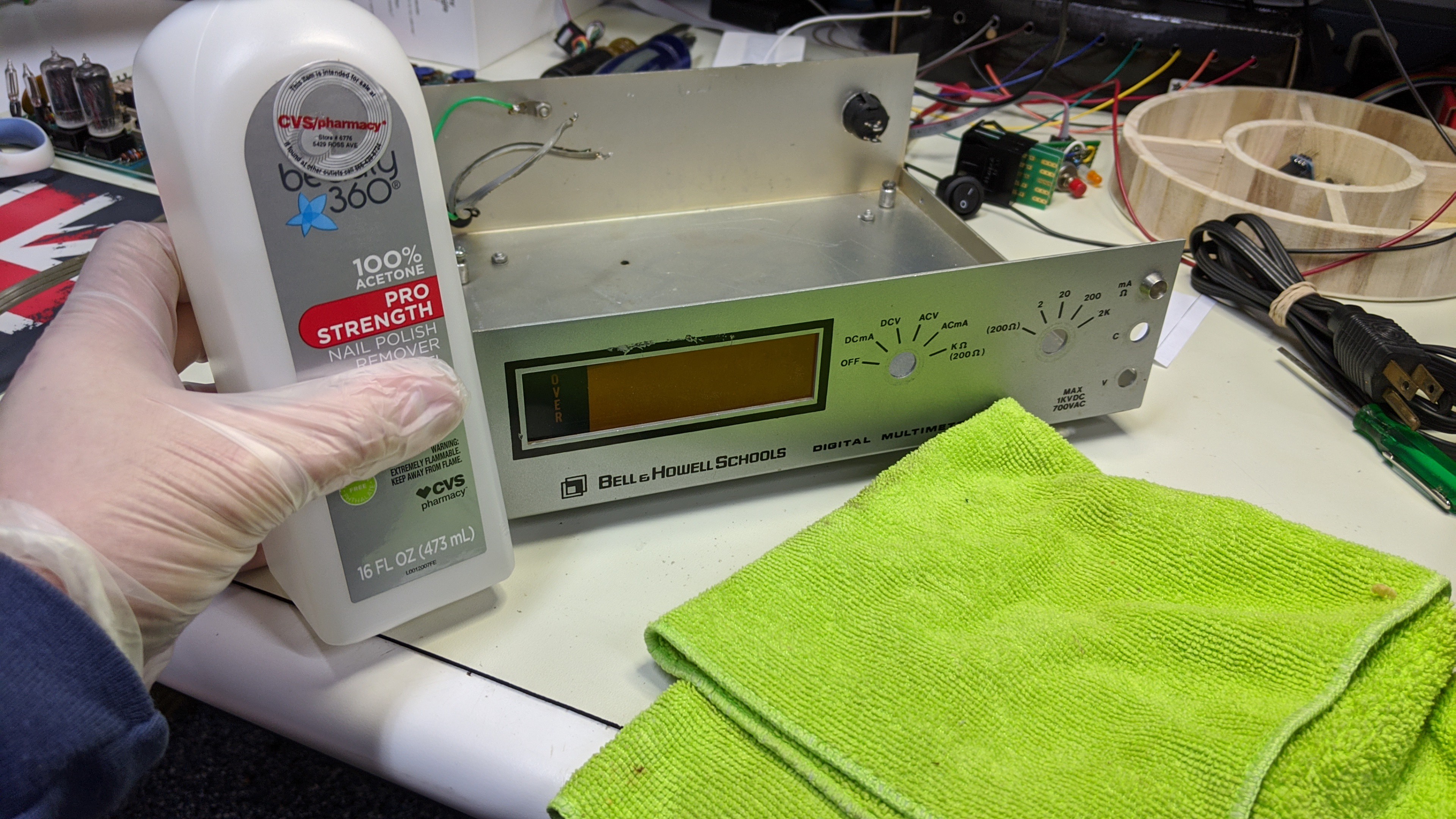
The first task was cleaning the old graphics off the original faceplate. I use some 100% acetone and rag to do that.
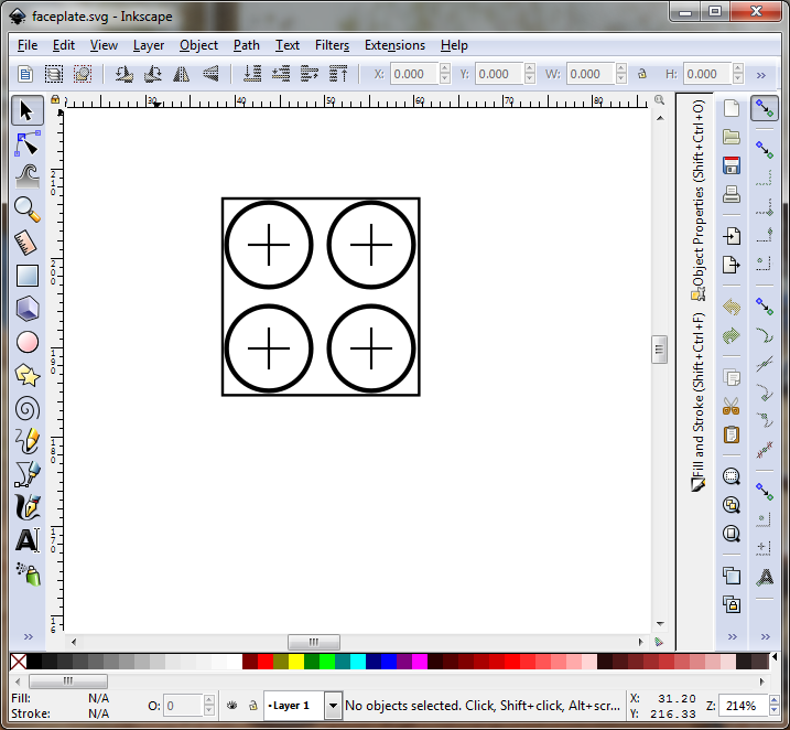
Then I drew up a template for the 22.5 mm x 22.5 mm square hole required for the 2 Digit Omron A7BS BCD encoded thumbwheel switch and end caps. I used Inkscape to draw it to scale and printed it.
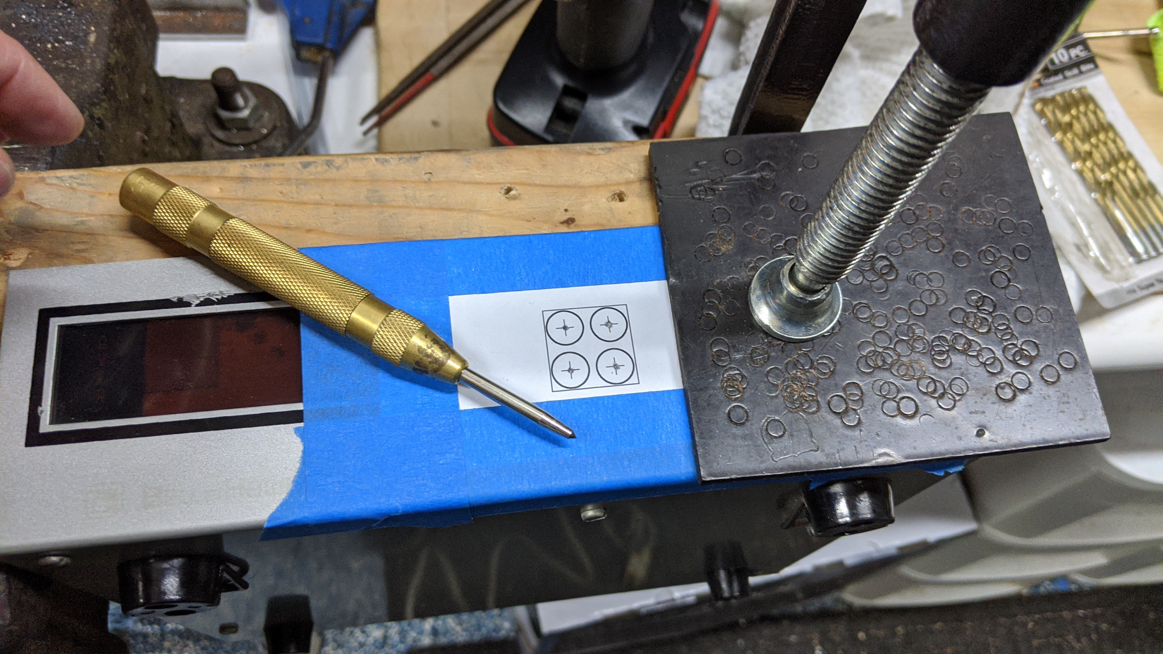
I then taped this paper template to the front faceplate of the case and secured it to a scrap piece of 2x4. I was generous with the template and painters tape used to secure it. This provides a protective barrier the prevents scratches on the faceplate while drilling, filing, cutting, etc.. Once secured in the vise, I punched the center point of the marked drill holes in the template.
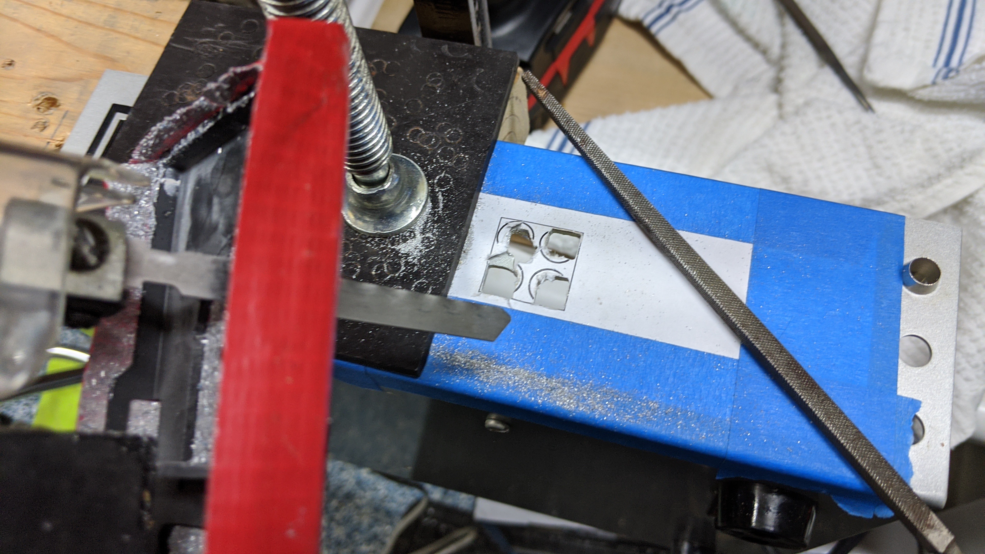
Next I drilled the holes and used a square file to start squaring off the corners marked by the template. I had to be a little careful to keep everything inside the lines of the template. The aluminum sheet metal files very easily.
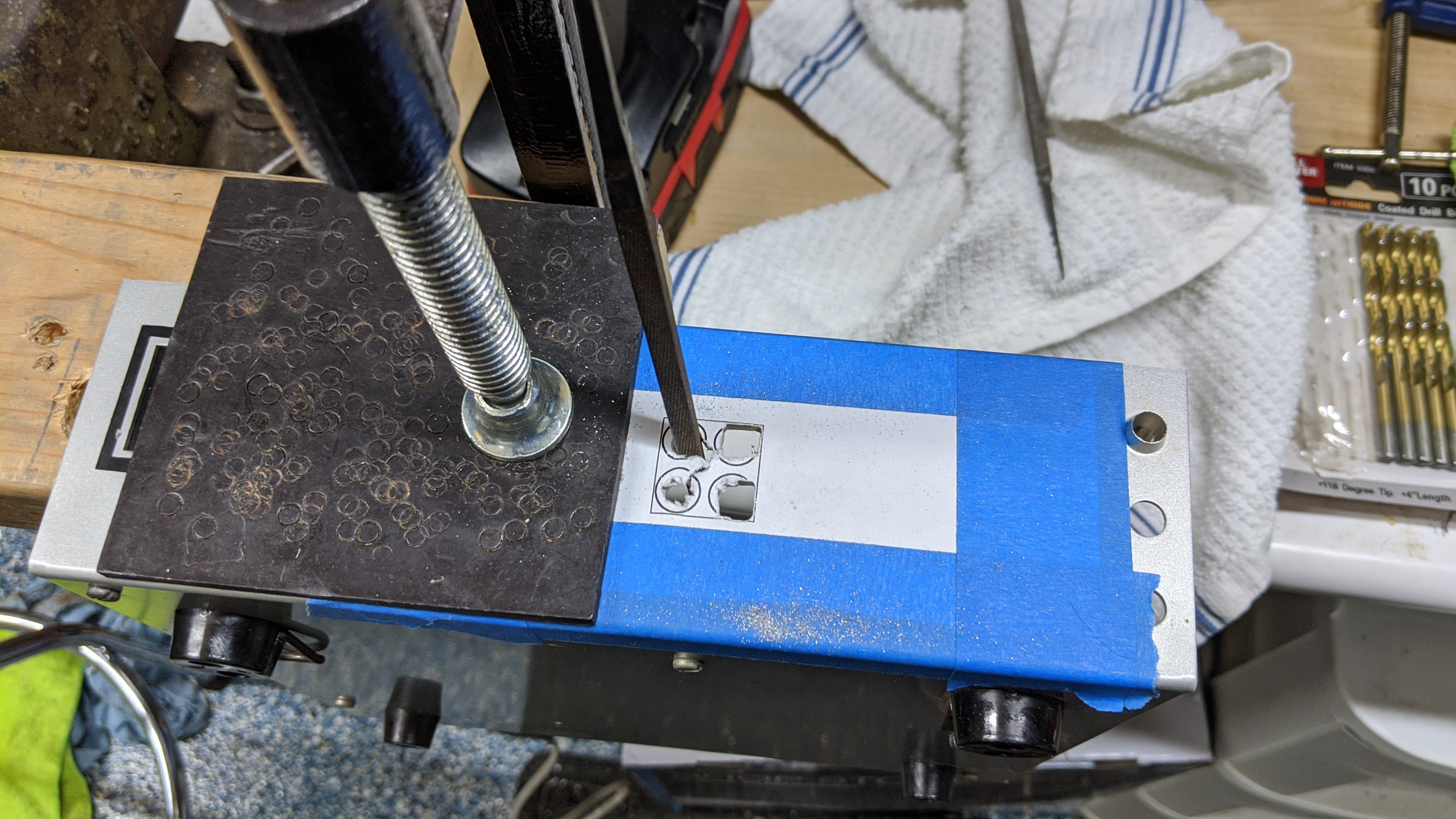
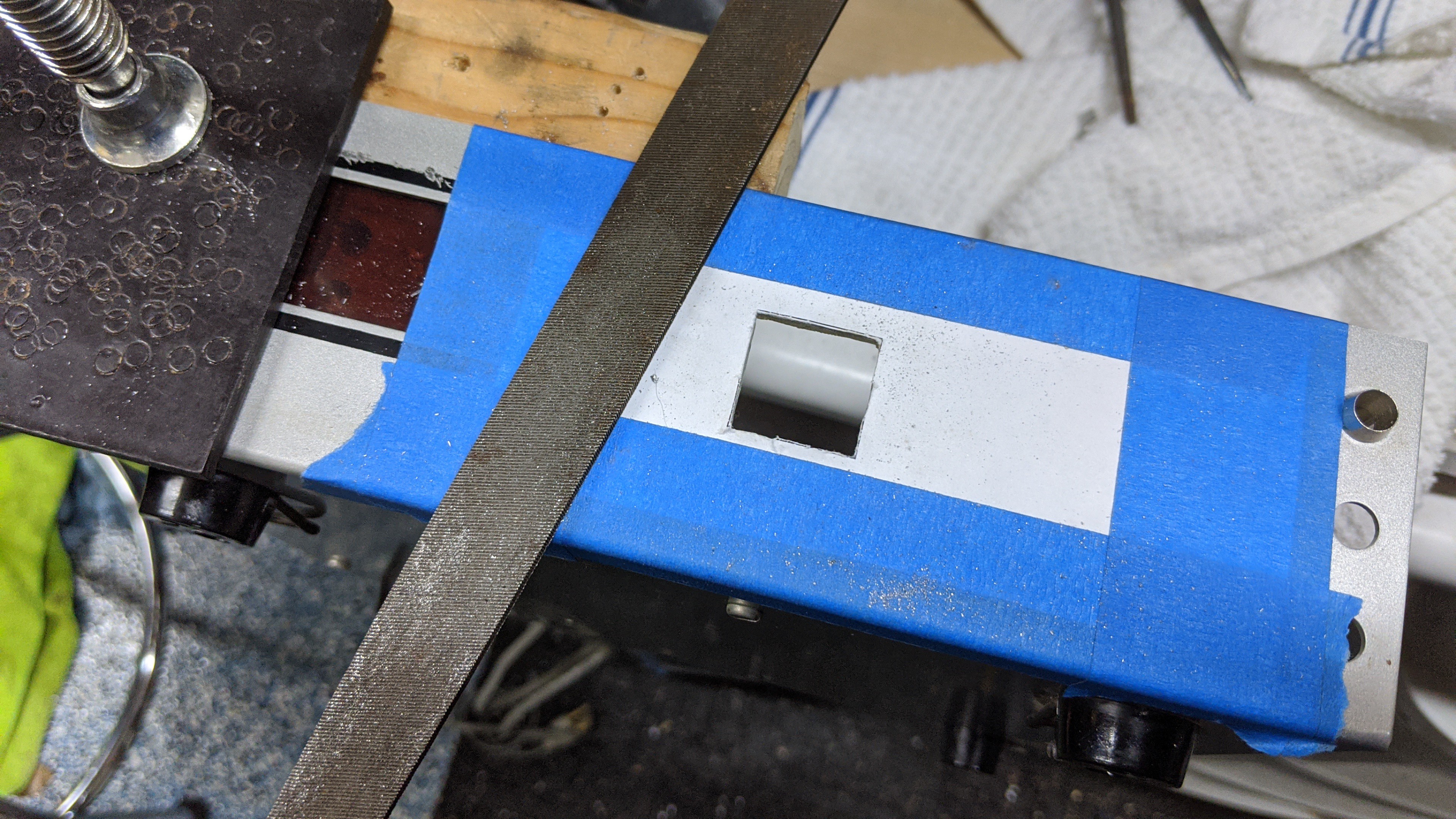
Once three of the four holes were squared to the corners of the template square, I used a jigsaw to cut out each side of the square. The filed holes were just large enough to fit the jigsaw blade flush to each side of the square. Again, I had to be very careful to cut slowly following the template line and not cutting past the perpendicular line of the next side.
Once the cuts were complete and I pulled out the remaining bit of metal, I used a larger metal file to clean up the square a little. I then test fitted the thumbwheel switch and filed a little more until it slid in snugly. My template was intentionally about .2 mm too small so I wouldn't end up with a hole too large. I knew filing the last .1 - .2 mm would be more precise than cutting. It was easy to file and took just a couple minutes to get it just right.
Once I was satisfied with the fit, I pulled off the tape and template paper.
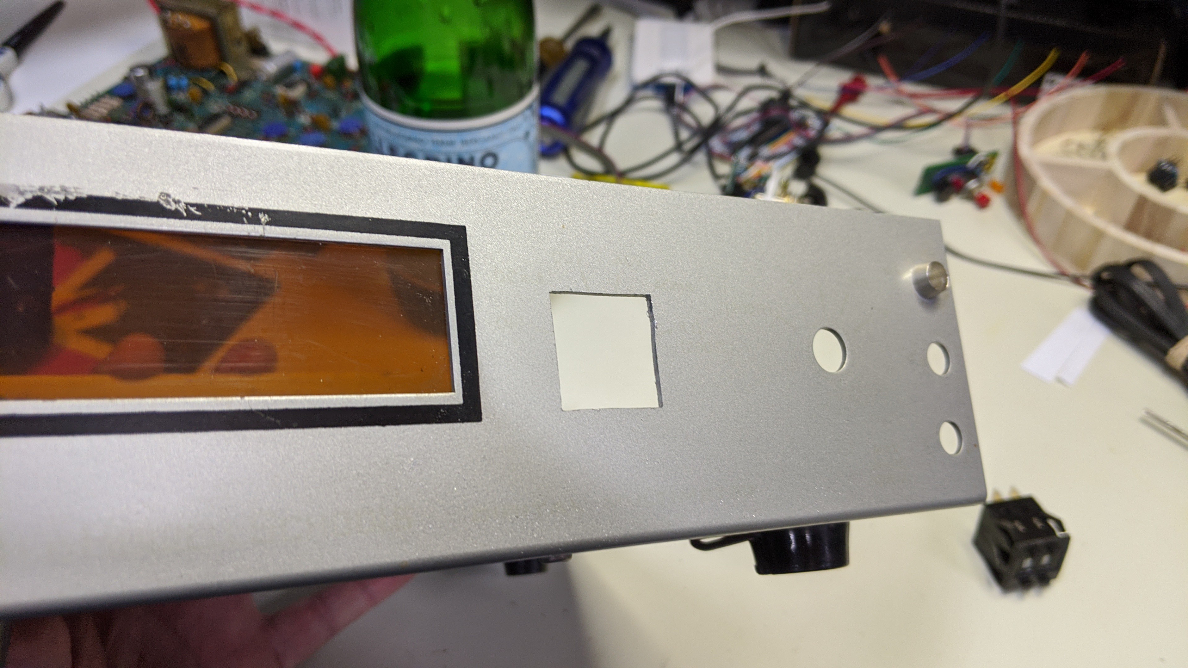
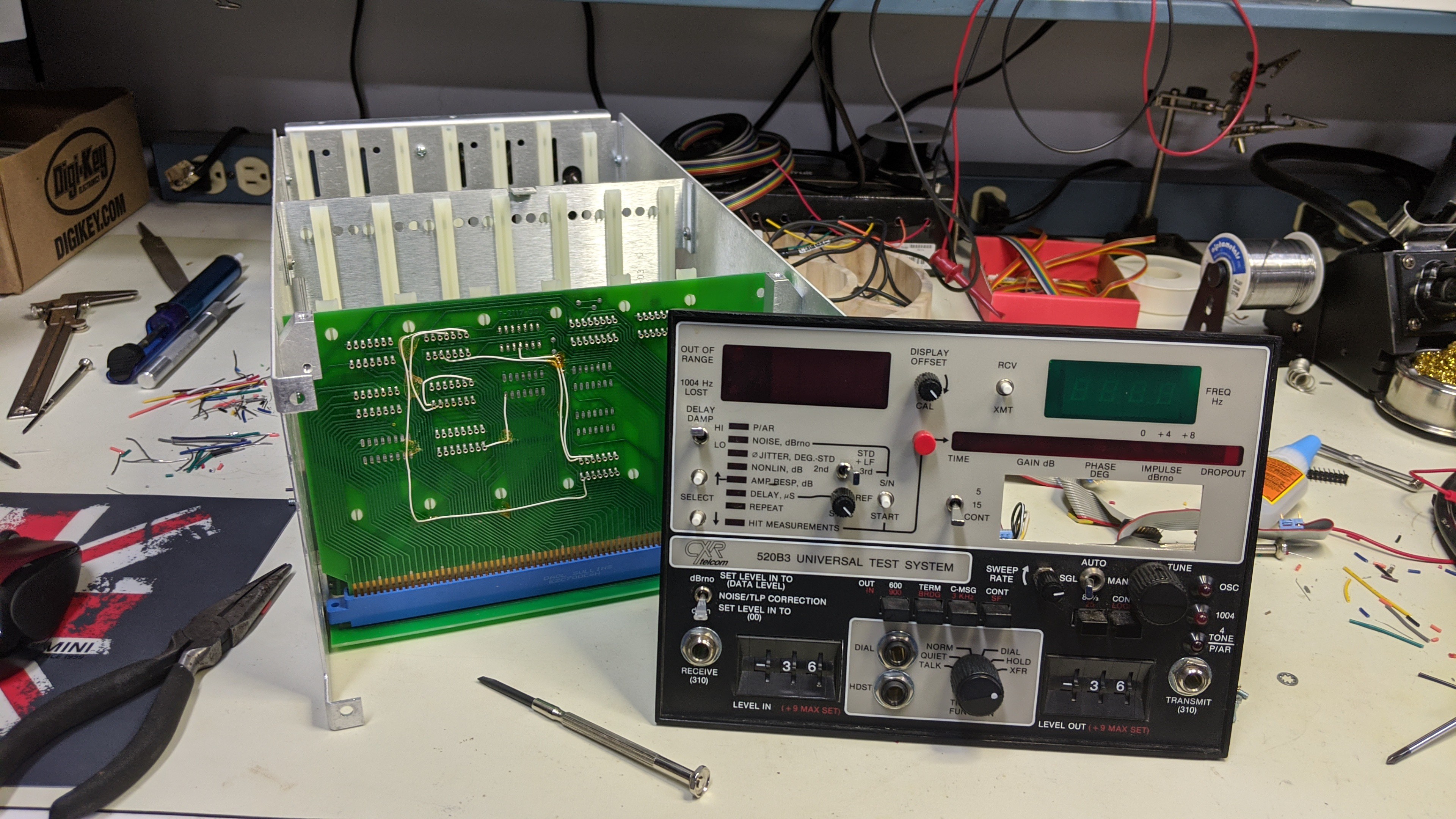
And, the fit for the switch looked like this. BTW, don't press the switch into place just yet. Once it snaps into place it's difficult to remove. I still needed to configure and solder the cable to the switch.
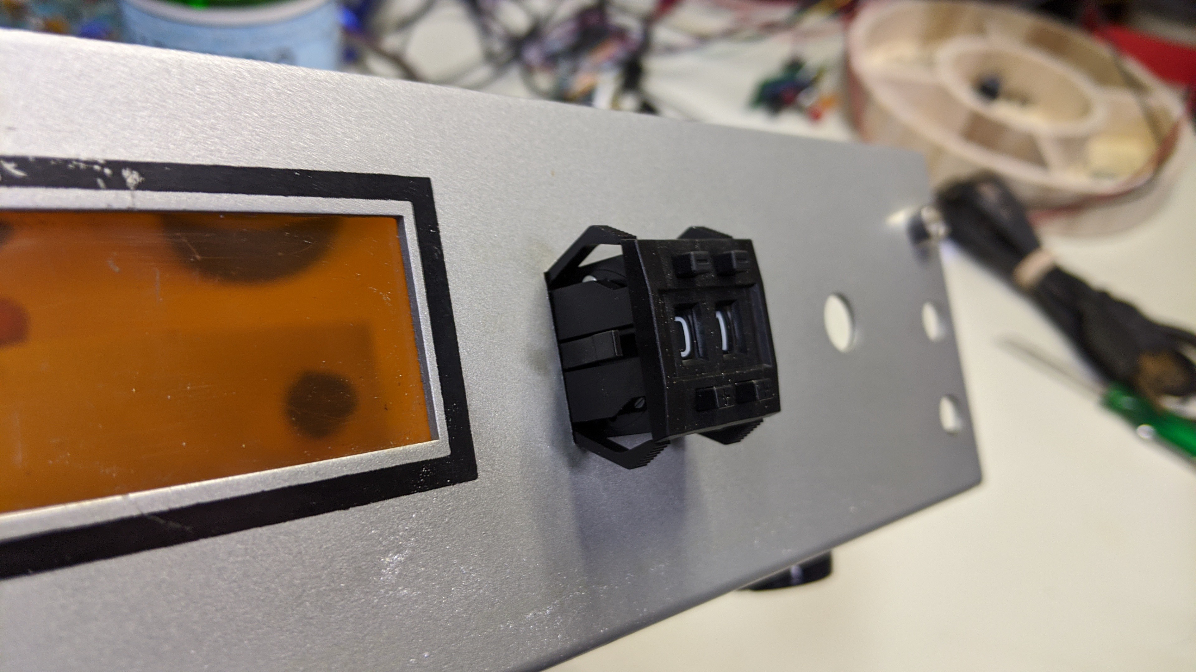
The rest of the holes will be used as is. In the pics above, you can see that I also test fitting the panel mount LED holder as well.
The three holes on the right are about 3/8" (9 mm). So, I needed a small panel mount push button that could fit. I pulled one off a panel from my spares stash that I keep for just such occasions. This panel came out of an old Cable TV line tester/analyzer that's no longer useful. I bought it cheap for the case, power supply, and vector scope CRT for another project. This panel will be replaced in the final version. So, I can used all the cool switches, knobs, pots, jacks, and LEDs for other projects :-)
Discussions
Become a Hackaday.io Member
Create an account to leave a comment. Already have an account? Log In.