 John Anderson
The next step was to configure/build the new user interface switches, button, and speaker and wire those to the controller board.
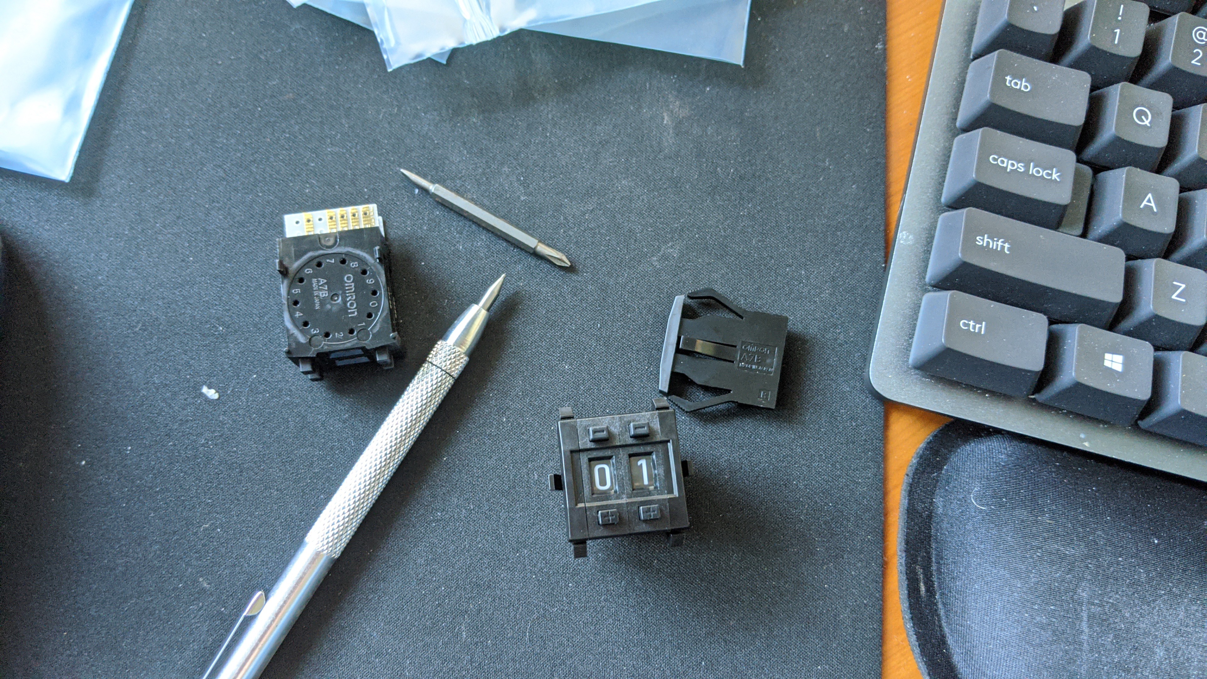
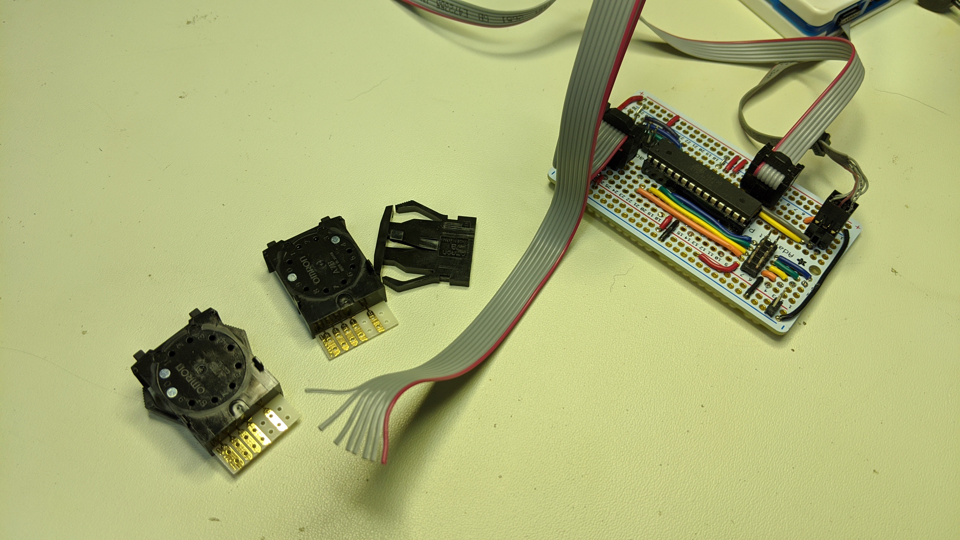
The two digit Omron Thumbwheel is configurable. It comes with pins that you install. This pins act as stops preventing the user from selecting a range of numbers. This is useful because I could reduce the range of selectable dice counts down to something realistic and reduce the number input pins required on the microcontroller. So, I installed the stops making the selectable tens digit range 0-3. This makes the user selectable range for the number of dice 0-39 and reduces the pins required for the dice count input from 8 to 6.
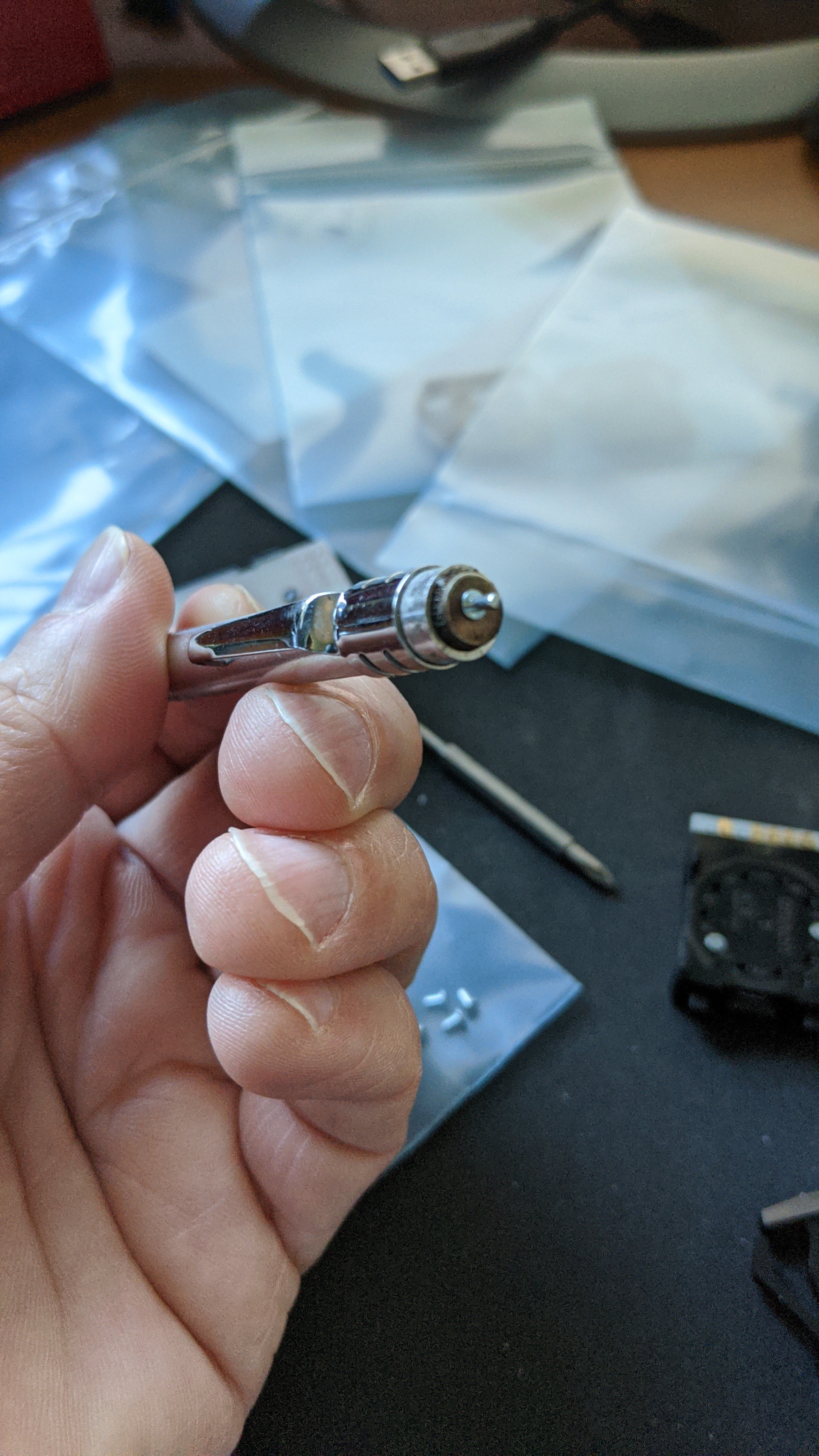
The pins that came with the switch are rather small and difficult to handle with my fingers. But, they are made of a ferrous metal. I discovered that I could used the magnetic end of my scribe tool to hold the pins and install them.
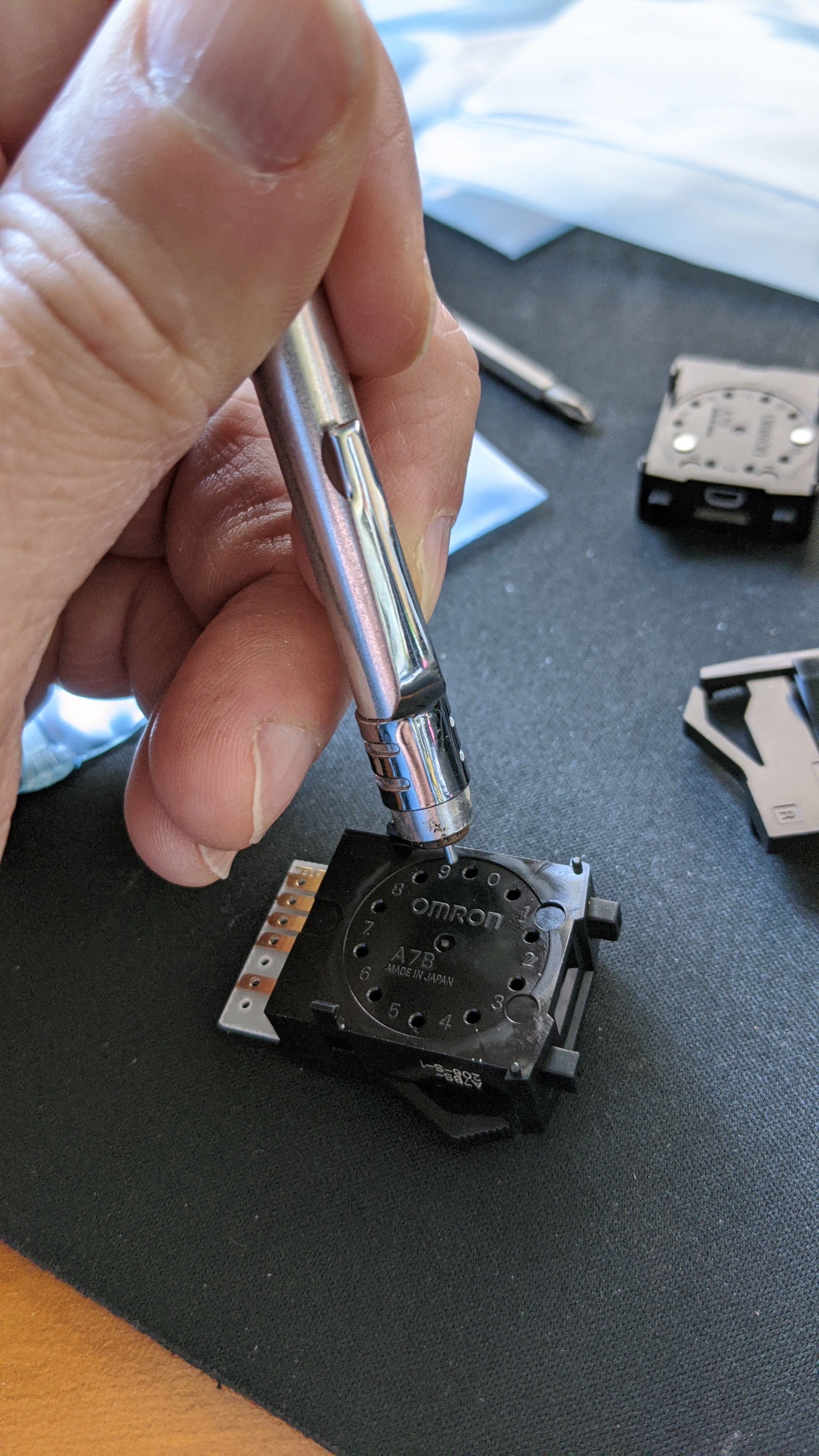
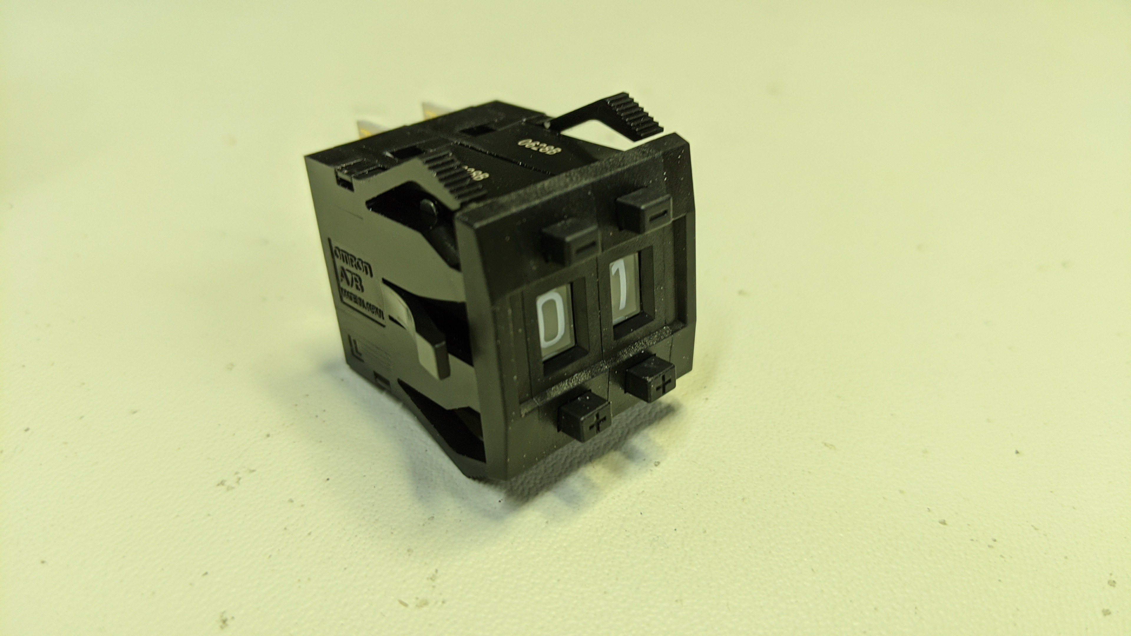
Once those were in place, the two digits snap together and the end caps snap onto each side of those.
Once the thumbwheel was all configured, it was a simple matter of soldering a 10 pin cable to the 4 BCD traces of the ones digit, the common on the ones digit, the 2 low order BCD traces of the tens digit, and the common on the tens digit.
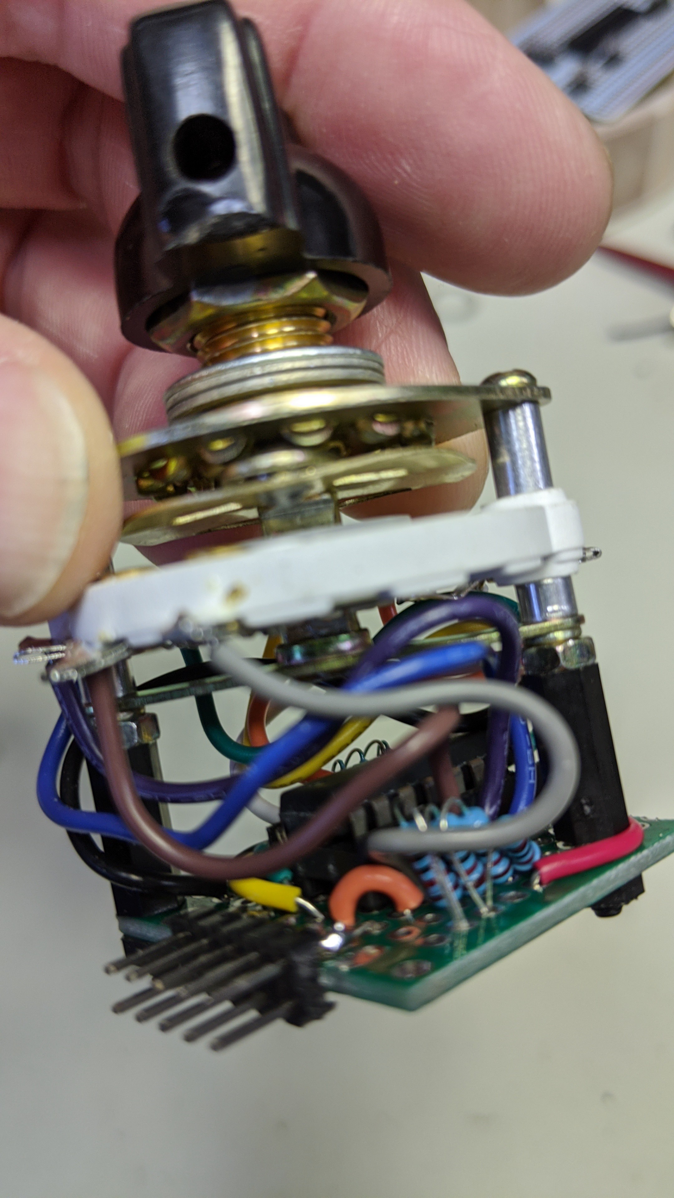
The rotary switch required a little more effort to wire up. Just like the previous version of the dice tower, I used a simple single pole 8 way rotary switch. However, I wanted to minimize the cable conductors and controller input pins required. So, I wired up a 74HC148 8 line to 3 line priority encoder on a small proto-board.
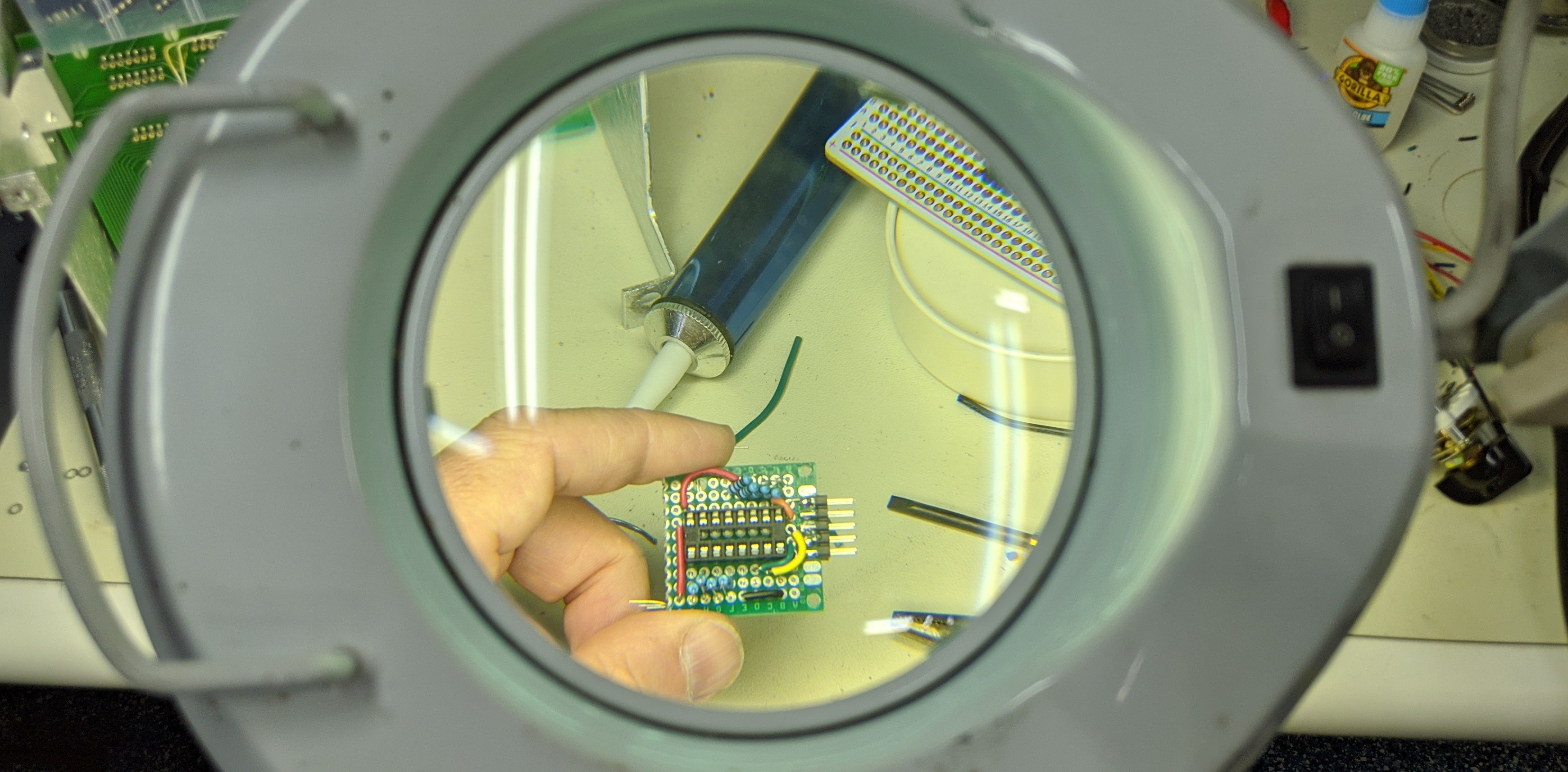
I then wired the board to the common and 8 selector lugs and used a couple stand-offs to connect it to the back of the switch.
Lastly, I cut another small piece of proto-board and soldered up a connector, LED, push button, and speaker to it so they lined up with the holes in the case.
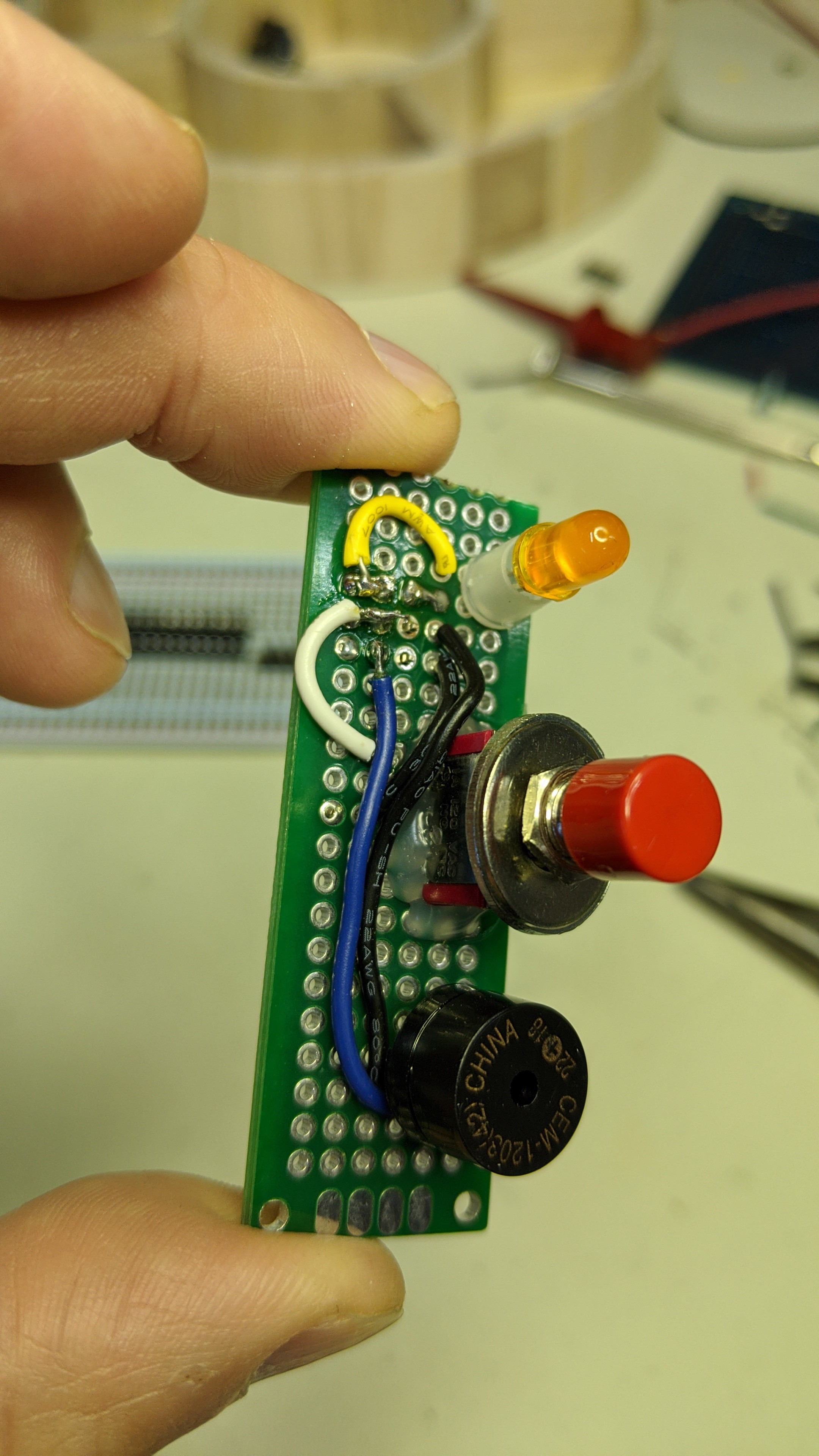
It looks like this installed.
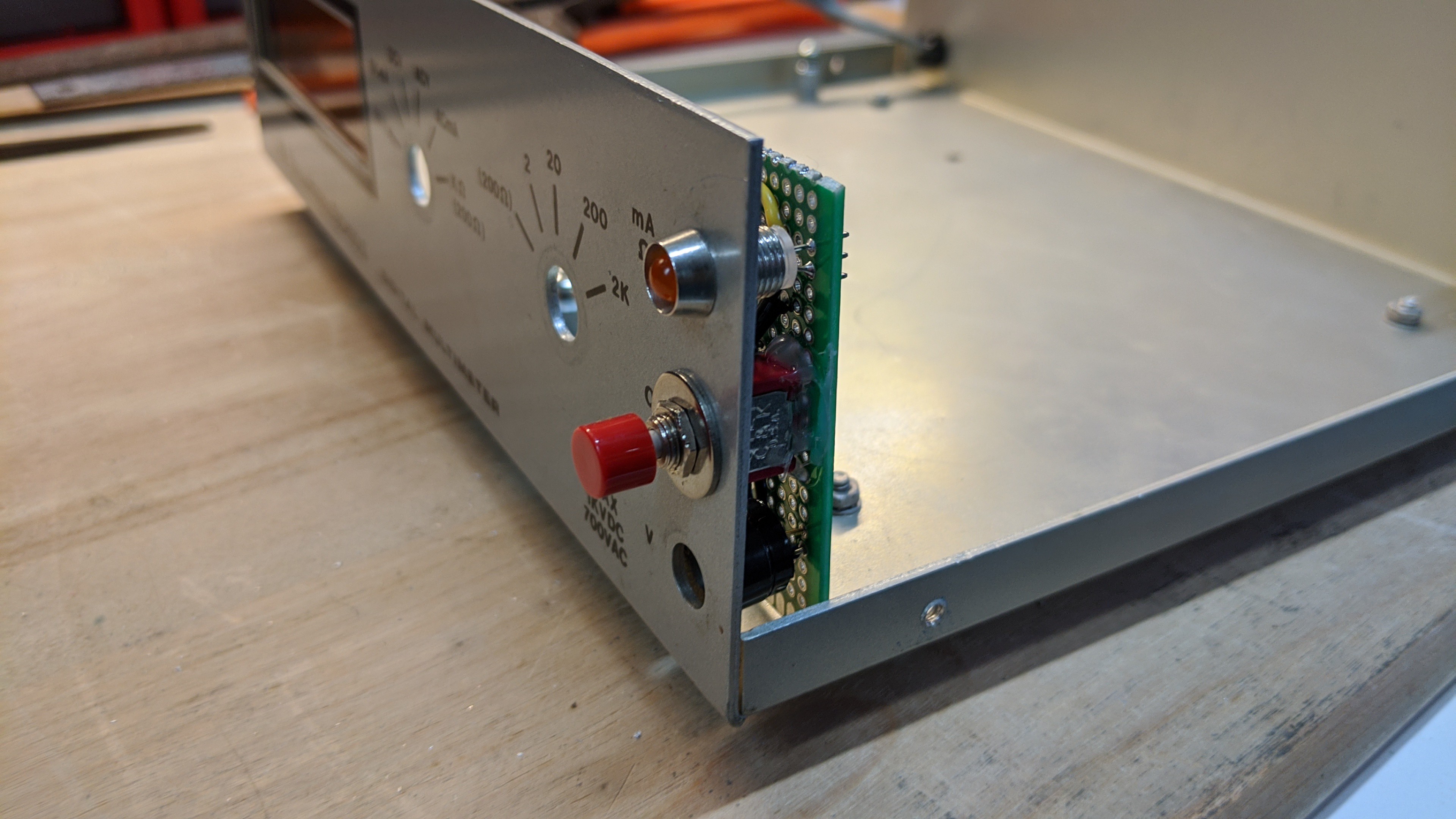
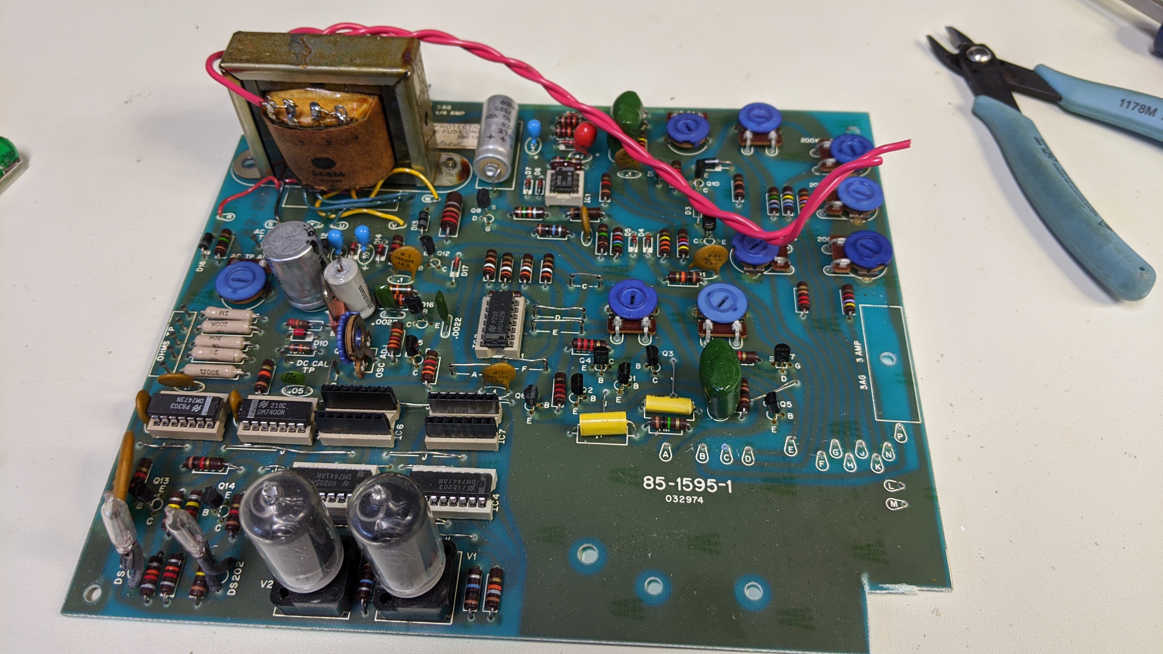
This required cutting a small notch in the front right corner of the original PCB so it would clear this new board.
Discussions
Become a Hackaday.io Member
Create an account to leave a comment. Already have an account? Log In.