I went out on a limb by not regulating the PIC and rather crossed my fingers just bypassing the power supply with two ceramic capacitors (.1uF and a 10uF). I also risked not using a crystal to control the micro's clock and instead used their precision, internal clock oscillator.And to detect (loosely) the displays position in space, I used two simple tilt switch sensor (one defined the beginning of where to start displaying data and the second to estimate where the end of data should have occurred and send the code back to starting the process all over.
The LEDs are current limited to 10ma so I can directly drive all 7 at once with the PIC's porta.
Power supply is a CR2032 Lithium battery.
SO HERE'S THE RUNDOWN OF HOW THINGS WORK:
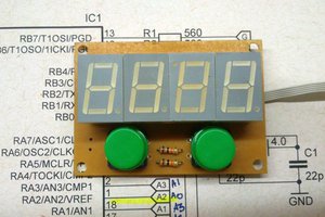
There are three tactile switches to the right of the display (see photo 1). The center switch says 'interrupt the watch's 'sleep', start the display'. The other two switches, when in 'set mode' set the current hours and minutes. They have the function of informing the micro's RTC whether a register should be set'up/down', increasing or decreasing a single numeral. To get into this mode requires holding down the center switch for 3 seconds. After, the center switch acts as an advancing to 10s of hours, hours, tens of minutes and then minutes. I did not included any other time information (seconds, date, etc.)although available in this PIC.
I am torn between using the display in it's active mode to 'see' what number the user is setting for initial time or using the devices display in a static mode (not moving) and setting it as a BCD (Binary Coded Decimal). The former is more difficult to use than one could imagine.
The PIC has internal EEPROM that when power is off, data that was stored there remains for reading it when running. I arduously, using graphed paper, blocked out 11 (0 to 9 and a ':'), 5X7 columns and rows representing each columns association with the PIC's I/O (input and outputs).
I first used two sensors to detect whether the device is in a left most position or a right most position. Why detect both positions? Because when the device is going in an opposite direction of where it started, the data representing the numerals need to be reversed. Using this method improves visibility by duplicating light output on it's return and so there is no 'blanking' of the display.
Well, that worked poorly and I believe the reason it didn't satisfy was because the internal clock of the micro was not crystal controlled and off just enough to make for confusing visibility as well as the uncertainty of manually moving the display over time.
One of the most important consideration for these sensors in code is to make sure they are well 'debounced' or you get a lot of ghosting in the final image.
Anyway, I tried using the second sensor simply to end a frame and begin another and although more demanding of speed and rhythm of the user it still performs best of all options. I sped up the 'fetching' of the data necessary from the EEPROM which in turn speeds up all the variables in getting this to work.
So the sensor tells the PIC start sequencing the columns of the EEPROM. The code first looks at the hours and minutes register from the internal RTC, stores these in a variable space and then these variables are used to fetch which numbers to display.
THE CAMERA IS QUICKER THAN THE EYE:
The relative slowness of the eye's perception of things and it's nature to make sense of and assemble data in the brain allows us to piece together the changing visual data and form a more constant image that makes sense to us. Not so for the high speed capture of a camera. To the eye (although with some blanking) the time displayed on this project is quite apparent. It was difficult to get any semblance of the image I saw, with video. I simply couldn't oscillate the movement fast enough to outsmart the camera's frame rate. So included is a photo of one frame of the video that just happened to be 'in the right...
 danjovic
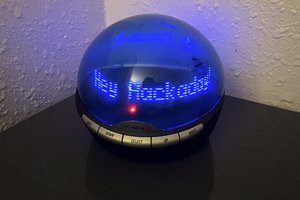
 Andy Kong