 James Wilson
As I began to think of a clock that would evoke the sense of time I had at camp, a few themes kept coming up. I had recently been introduced to bar Nixie tubes, such as the IN-9 and IN-12. By varying the amount current through the tube, you could change the length of the glowing segment. Their warm, retro glow were the perfect match for the time readout I wanted. I was also inspired by the minimalist industrial design of Braun desk clocks, from an exhibit on the work of Dieter Rams at San Francisco's Museum of Modern Art. Lastly, I wanted to power the clock from a USB phone charger. I was not yet comfortable with working with mains power directly, and my previous dabbling in Nixie tubes left me with an wasteful assortment of incompatible wall-wart power supplies. Since USB phone chargers were ubiquitous, I wanted to reuse them instead of contributing to more e-waste.
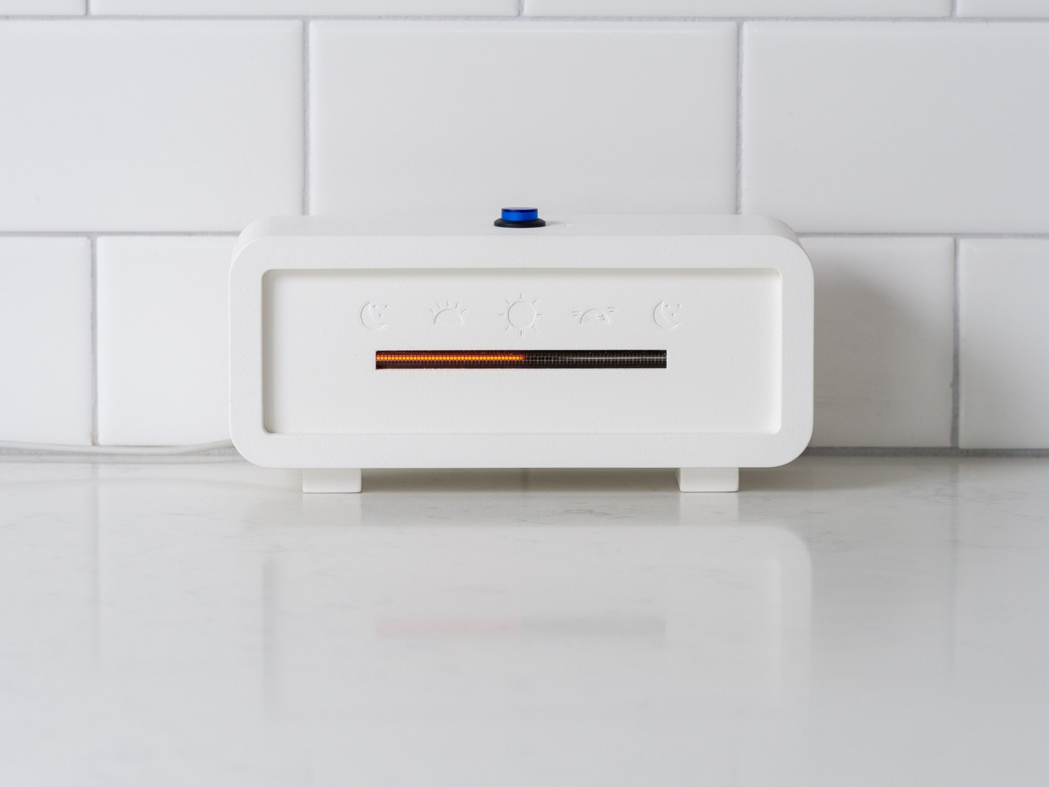
The project, "Leave Time Behind" takes the form of a desk clock. A custom printed circuit board (PCB) houses the main components of the electronics design: a switched-mode DC-DC power supply, a microcontroller with Bluetooth low-energy connectivity that keeps time, and a driver circuit that converts the digital time output from the microcontroller to an analog control signal.
The time is displayed on an IN-13 Nixie tube as a continuous glowing bar that grows longer over the course of the day. Compared to a traditional clock that allows us to obsess over hours and minutes, Leave Time Behind only permits the viewer to mark time and intervals approximately in relation to the natural cycle of the day.
When I thought of the design of the clock, I wanted it to have the minimum interface possible. In keeping with the aim to de-emphasize attention to hours and minutes, there are no discrete controls to set the exact time. To set the time, a single button on the top of the enclosure activates the Bluetooth function. When paired with a smartphone, the clock reads the time from the device.
The power supply
The power supply consideration ended up being the most difficult aspect of the design. Nixie tubes typically require an initial firing voltage of 150 to 170 V, with a sustaining voltage of around 100 V and current of a few mA. Stepping up USB's 5 V to about 150 V is no easy feat. I would need a DC-DC boost converter, and I couldn't find a ready-made design that supported in an input voltage of 5 V. I would have to design my own switching power converter. Every guide I read said that these circuits are not for beginners, but undaunted, I decided to try.
The first attempt at making a power converter was unsurprisingly a fiasco. How much inductance did I need? What size of output capacitor should I use? And what inspired these chosen R & C values for the controller compensation pin? Without a formal background in the theory of switching power supplies, I worked off of formulas in application notes and tried to fill the gaps with educated guesses. This would also be my first time designing a PCB for fabrication, so I had that additional learning curve. Amazingly, the first board "worked" in the sense that it produced about 140 V across the output with an open circuit and would light an IN-13 tube. But it was clearly not a great design; it couldn't source more than 2 mA without losing voltage regulation, and it was injecting a lot of nasty harmonics back into the input line.
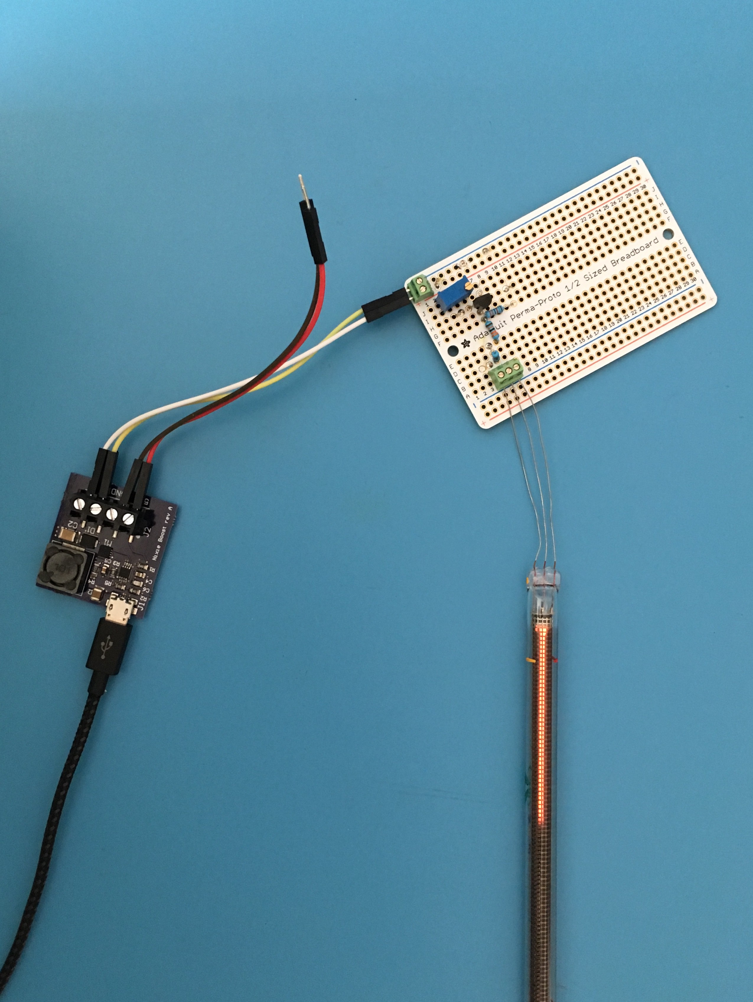
The first test of the power supply lighting an IN-13 tube
This might have been a good point to punt and accept using a commercially available power supply, but something about the seeming wizardry of switching power supplies reeled me in. Over several months, I worked through a rigorous online course series (via Coursera/CU Boulder) on modern power converters, and came back to the project equipped to build something better. As I learned, trying to build a continuous conduction mode (CCM) boost converter with a conversion ratio of over 30 was a pretty bad idea. The best options...
Read more »

 oneohm
 Litan Virgil
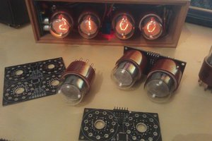
 Thomas Flayols
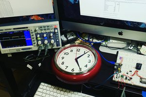
 liebman
Awesome work, I really like the DC-DC converter design process. I learned all about it recently, now I need a project to implement it in.