 UTSOURCE
Let’s start…
Components Required:
- BC547 Transistor (2) https://www.utsource.net/category/elec-component/transistors
- NE555 Timer (1) https://www.utsource.net/category/sensors/other-sensor
- 100 micro farad Capacitor (1) https://www.utsource.net/category/passive-components/capacitors
- 0.1 micro farad Capacitor (2) https://www.utsource.net/category/passive-components/capacitors
- Condenser micro phone (1) https://www.utsource.net/category/sensors/other-sensor
- 1k, 6.8k, 47k resistor (1) https://www.utsource.net/category/passive-components/resistors
- 470E, 330E resistor (1) https://www.utsource.net/category/passive-components/resistors
- LED (1) https://www.utsource.net/category/led-lighting/led-modules
- 9v Battery https://www.utsource.net/category/accessories-tools/battery-case
10.9v battery clip https://www.utsource.net/category/accessories-tools/battery-case
11. Connecting wires https://www.utsource.net/category/accessories-tools/wires-cables
12. Bread Board https://www.utsource.net/category/accessories-tools/breadboard
Circuit Diagram:
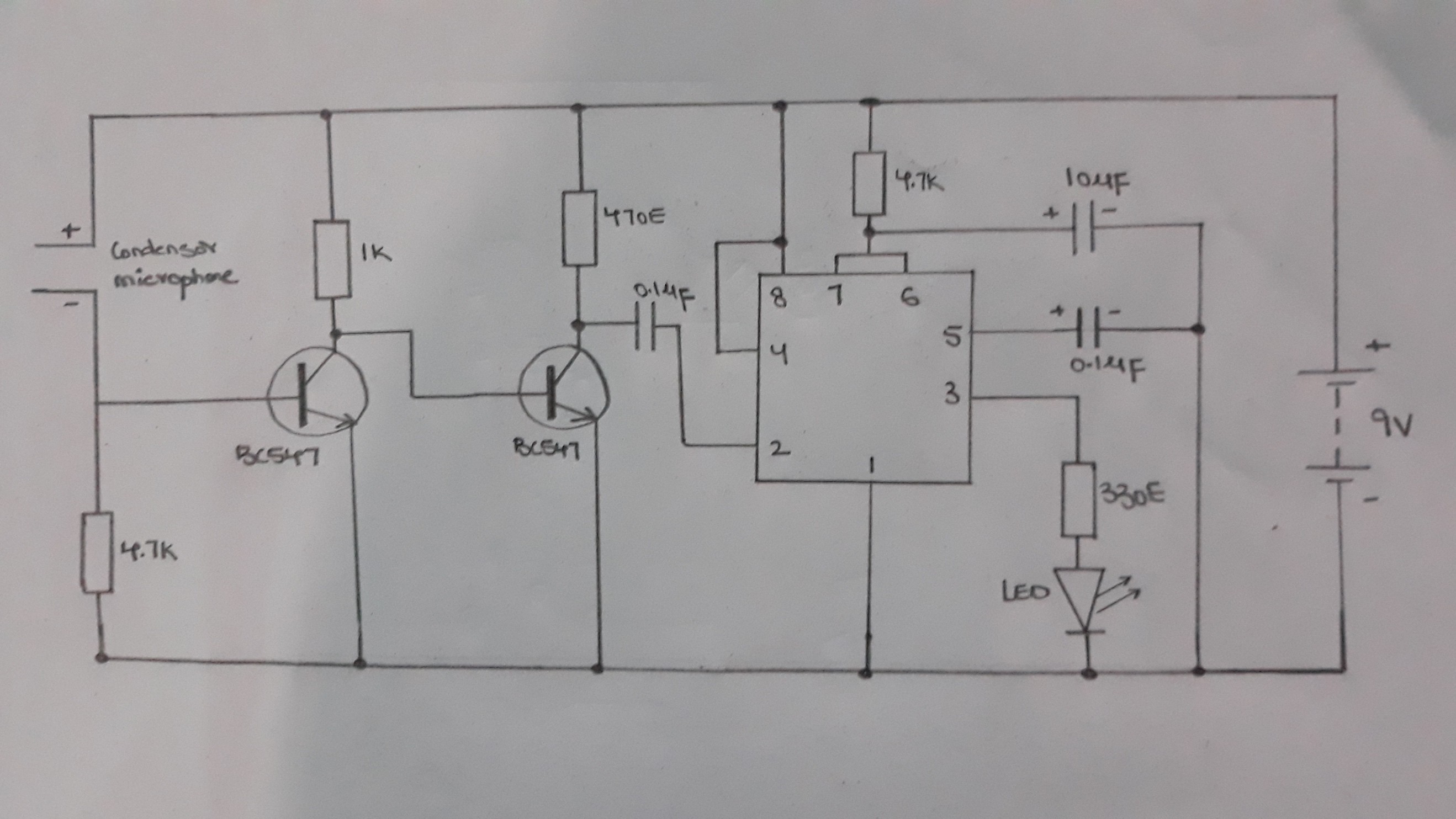
Procedure:
- Insert the NE555 timer and the two BC547 transistors on the bread board.
- Connect the emitter of the two BC547 transistors to the negative rail of the bread board.
- Connect the 6.8k resistor from the base of the first BC547 transistor to the negative rail of the bread board.
- Connect 1k resistor from the collector of the first BC547 transistor to the positive rail of the bread board.
- Connect the collector of the first BC547 transistor to the base of the second BC547 transistor.
- Connect 470 ohm resistor from the collector of the second BC547 transistor to the positive rail of the bread board.
- Connect the pin 1 of the NE555 timer to the negative rail of the bread board.
- Connect pin 4 and pin 8 of the NE555 timer to the positive rail of the bread board.
- Connect pin 6 pf the NE555 to pin 7 of the NE555 timer
10.connect the 47k resistor from pin 6/pin 7 of the NE555 timer to the positive rail of the bread board.
11.Insert the 100uF capacitor on the bread board with its positive terminal connected to the pin 6 of the NE555 timer.
12. connect the negative terminal of the capacitor to the negative rail of the bread board.
13. Insert the 0.1uF capacitor on the bread board with one of its terminal connected to the pin 5 of the NE555 timer and the other terminal connected to the negative rail.
14. Insert the other 0.1uF capacitor on the bread bread board with one of its terminal connected to pin 2 of the NE555 timer
15. Connect the other terminal of the 0.1uF capacitor to the collector of the second transistor.
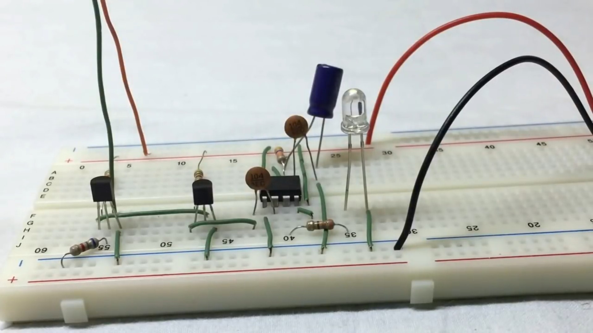
16. Insert the LED on the bread board
17. Connect the cathode of the LED to the negative rail of the bread board.
18. Insert the condenser with its positive terminal connected to the positive rail of the bread board and negative to BC547 transistor
19. Connect the battery to the 9v battery clip and then to the bread board.
20. When we clap the LED blinks
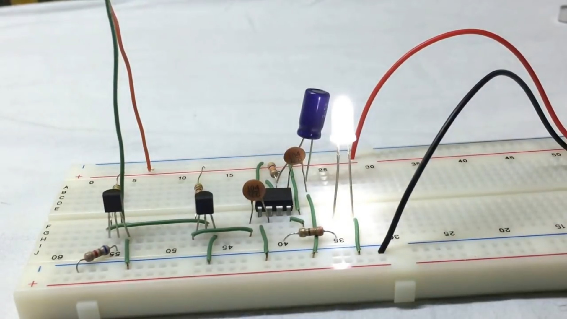
clap again to make the LED off, like this
Thank You…
 SimonXi
 muzi
muzi
 Dave's Dev Lab
 David
David