 Christoph Tack
Schematic
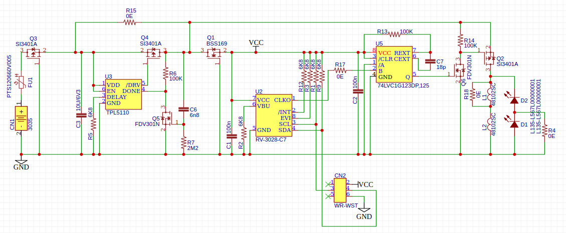
Power & protection section
The board is powered by a CR2032-cell inserted in CN1. FU1 is a 50mA fuse, it could be replaced by a 100ohm resistor.
Q3 is a reverse polarity protection to protect the circuit when the CR2032 is incorrectly inserted.
C3 smooths out the current spikes from the LEDs.
Flashing section
If flashing is not needed, instead of this section, place R15.
Functionality of this section is described in Testing the TPL5110.
The TPL5110 requires about 35nA.
Oscillator section
The RV-3028-C7 is an RTC. After its internal EEPROM is programmed, it will output a 64Hz square wave on the CLKO-pin.
This RTC can be programmed using the debug connector CN2. Any I²C-master could be used to program the RTC. CN2 is designed for the WR-WST IDC connector. It allows for easy connection and removal of a programming adapter.
The RV-3028-C7 requires about 45nA.
One-shot section
The 74xx123 is a one-shot timer. To reduce power consumption, its supply voltage is lowered to about 2V using Q1. Because U2 drives U5, U2 also needs to run on this lower supply voltage to prevent over-driving the B-input of U5.
The value of C7 requires some experimenting to fine tune. R17 can be removed to connect a function generator to pin B of U5, which will make experimenting easier.
The one-shot timer will produce a positive outgoing pulse when triggered.
The pull-up resistors are all 6K8. Their value isn't critical, so I reused the 6K8 from the flashing section to reduce the number of different BoM-items.
The current consumption needs to be measured it. At room temperature, it will only be a few hundred nA probably.
LED driver section
To drive the LEDs an NMOS with a low RdsOn could be directly connected to pin 5 of U5. To limit the number of different components in the design, I opted for reusing the FDV301 and the SI3401 instead. If this design would be produced in large quantities, the extra cost of logistics for an extra BoM-item would be far greater than the cost of an extra SI3401.
The 0ohm resistors allow to choose the number of inductors or the number of LEDs.
The inductors require a lot of PCB-space. Keep in mind that two of these 1mH coils are cheaper than one 2mH inductor with comparable specs. This is a design trade-off again: size for cost.
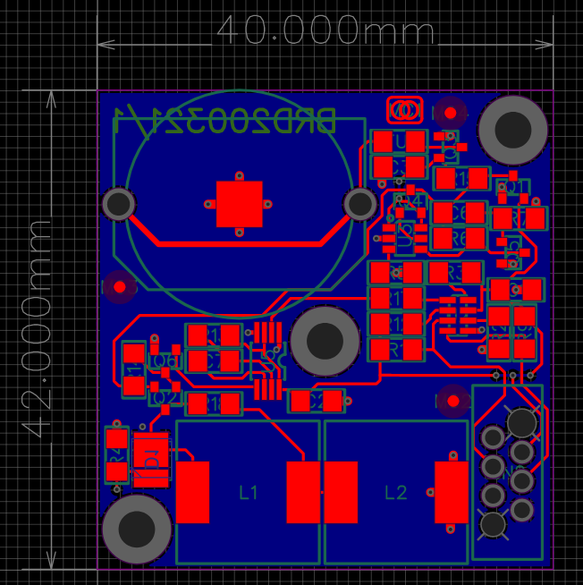
PCB-Layout
The size of the PCB should match a TikTak-box.
There are two diagonally placed mounting holes. Their use is not defined yet.
The 3mm mounting hole in the center if for mounting a neodymium magnet with a 3mm center hole.
One LED is on bottom side. The other one is on top side like the rest of the components. So one LED will be visible at all times.
Discussions
Become a Hackaday.io Member
Create an account to leave a comment. Already have an account? Log In.