 Yann Guidon / YGDES
The project description changes with the project itself... New and better ideas have emerged and the original idea is now obsolete but here it is :
(obsolete)
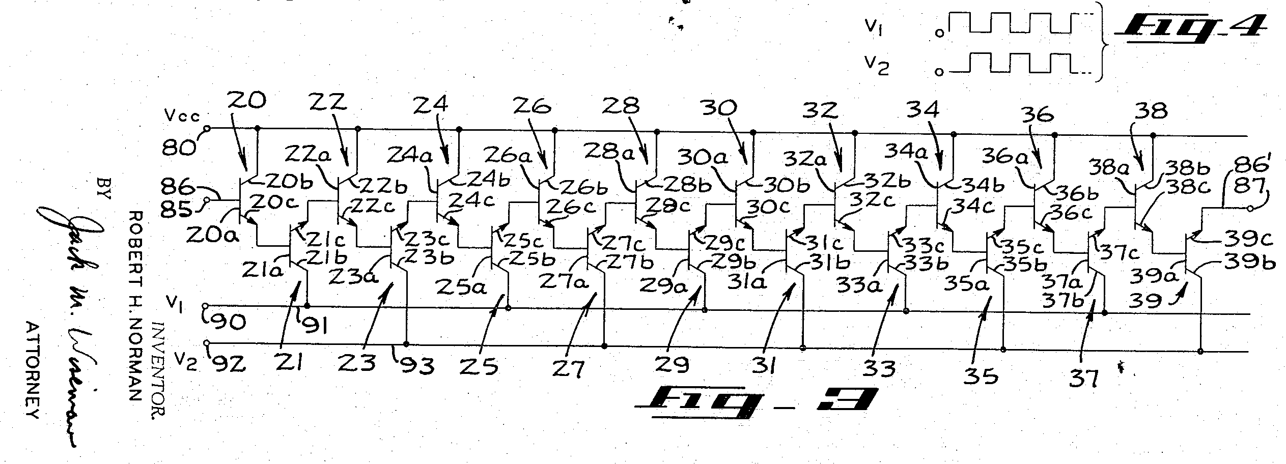
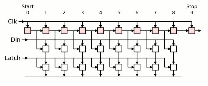
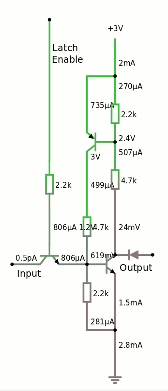
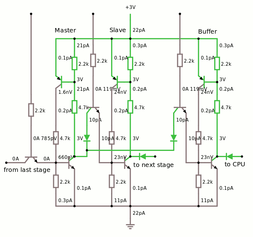
The principle is very simple and both the receiver and the emitter are based around the same module, made of 3 transparent latches, replicated 8 times. Then it's only a matter of properly sequencing the right signals.
Here is the version for the receive circuit :
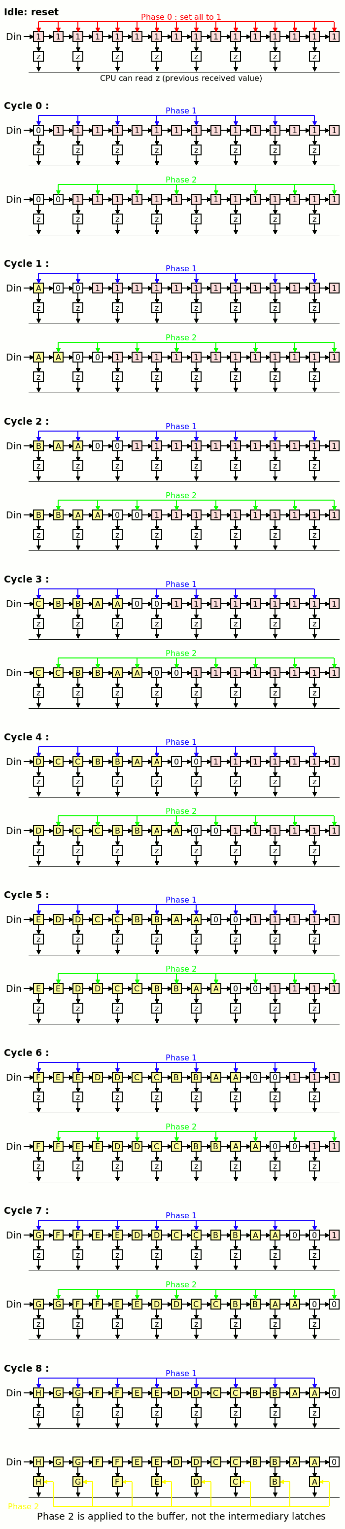
The CPU can read the receive buffer while another byte is being shifted in, which increases the bandwidth.
The same system is used, in reverse, for the emitter, but instead of using the last bit of the shift register as a "terminal flag", a AND performed.
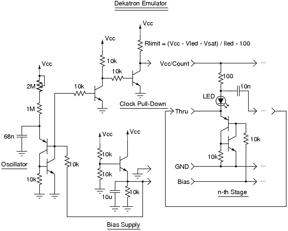
Each "bit slice" contains 3 "SCR-like latches":
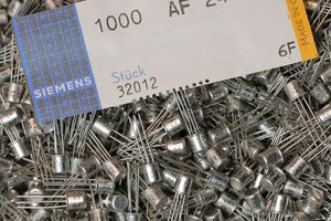
- 3 PNP
- 6 NPN
- 6 diodes (?)
- 15 resistors
Multiply by 8 (bits) and then 2 (emit & receive) again and you get:
- 48 PNP
- 96 NPN
- 96 diodes (?)
- 240 resistors
The baud generator is not yet included.
Logs:
1. First log: a minimal parts count shift register !
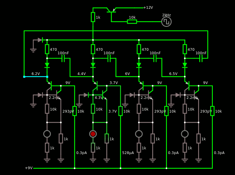
2. First slice
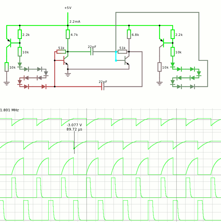
3. Clock Driver
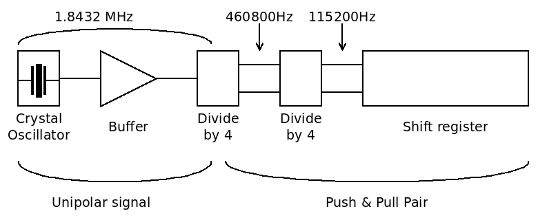
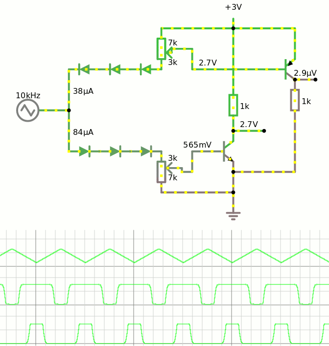
4. Baud generation
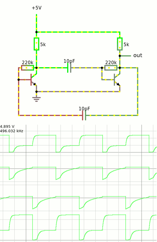
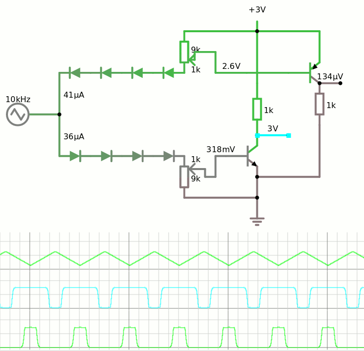
5. Oscillator mysteries
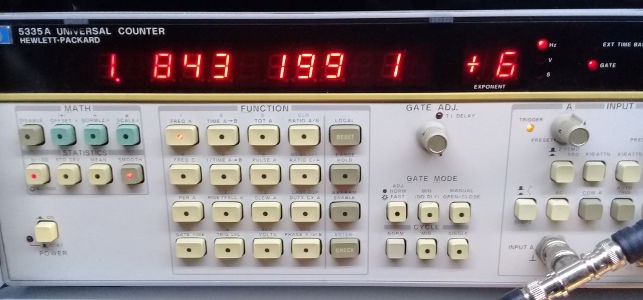
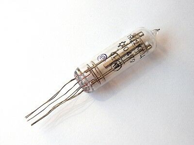
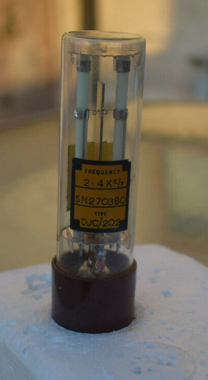
6. Frequency sources
7. Frequency sources épisode deux
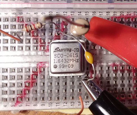
8. Canned oscillator
9. Tx with fewer parts
10. An even better SCR-based sequencer
11. Bipolar Capacitor Bucket Brigade
.
 HummusPrince
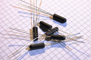
 Tim
Tim