 Electroniclovers123
Steps:
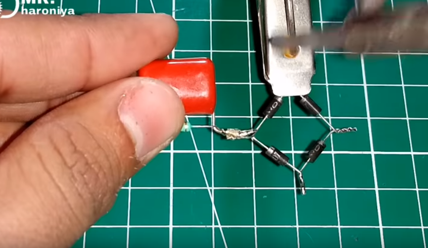
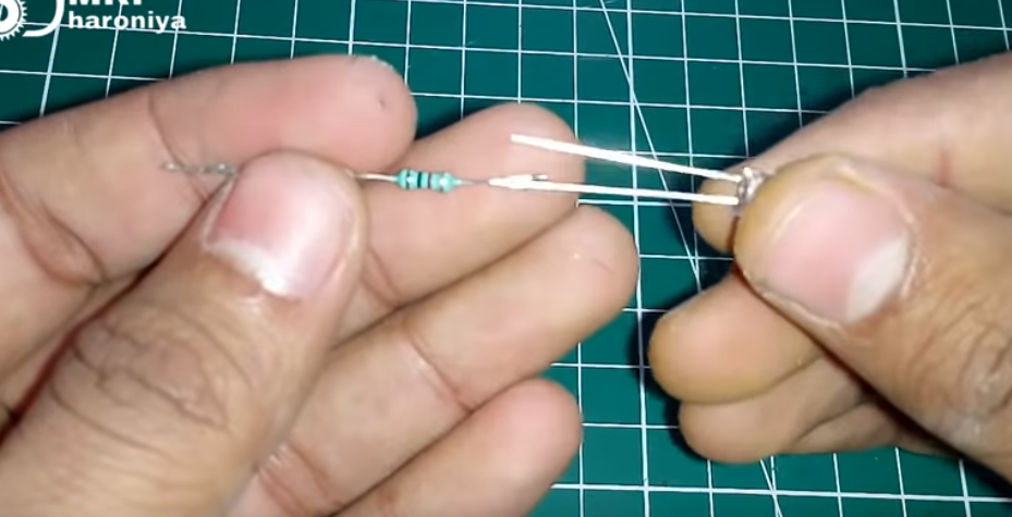
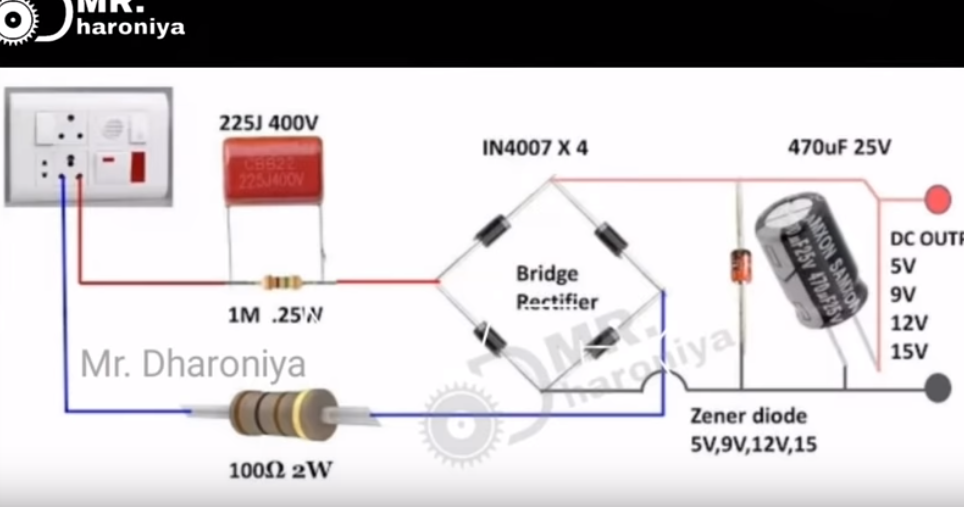
1, Prepare in4004 4pcs, and solder.


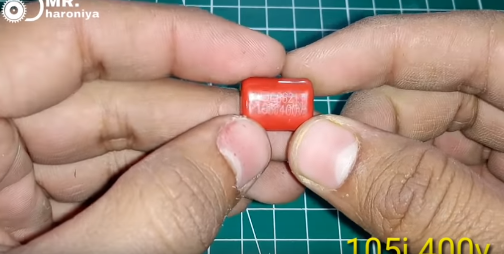
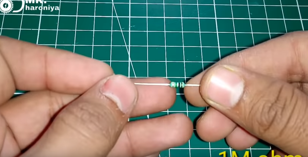
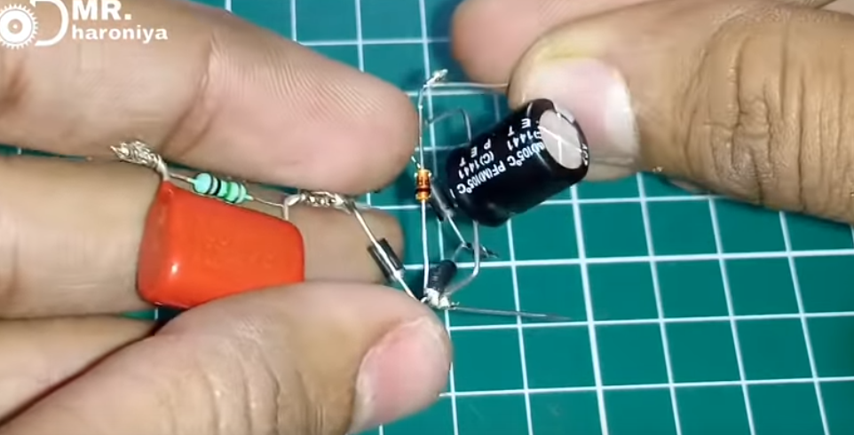
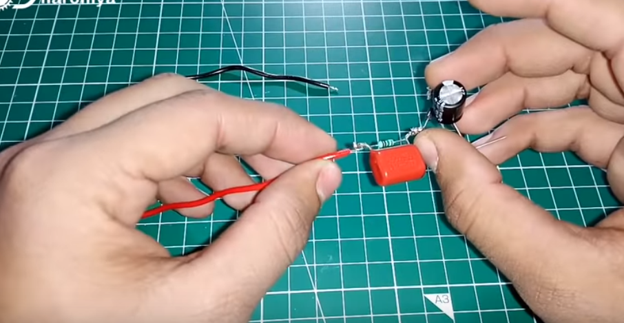
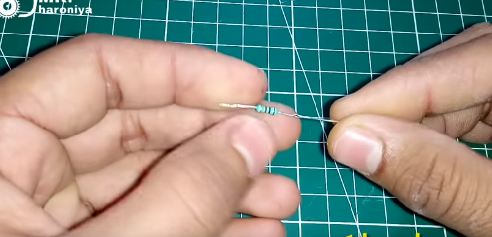
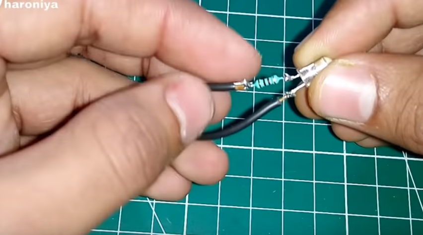
2.Prepare 105J 400V,1M ohm and solder them.
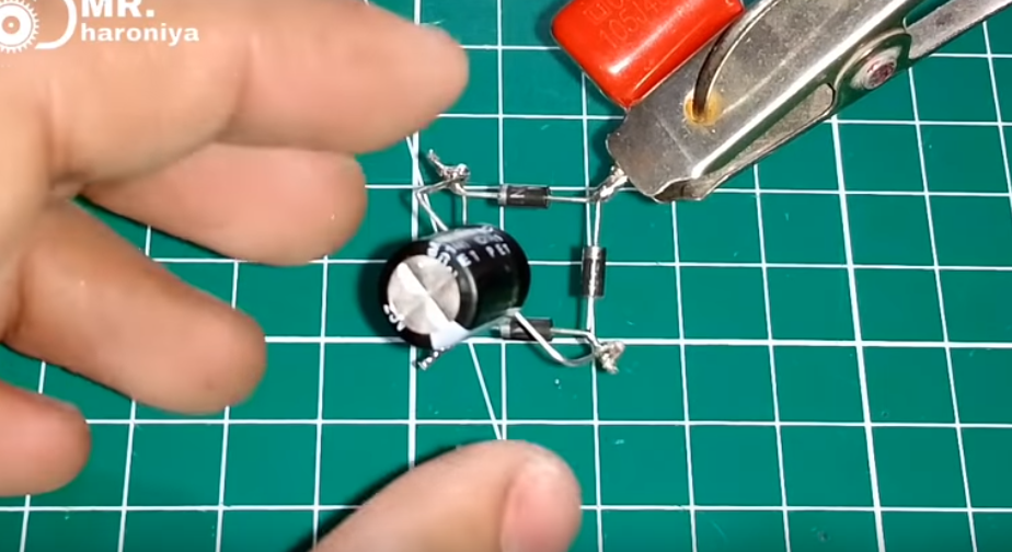
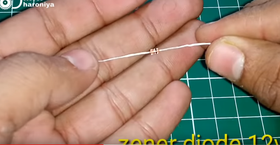
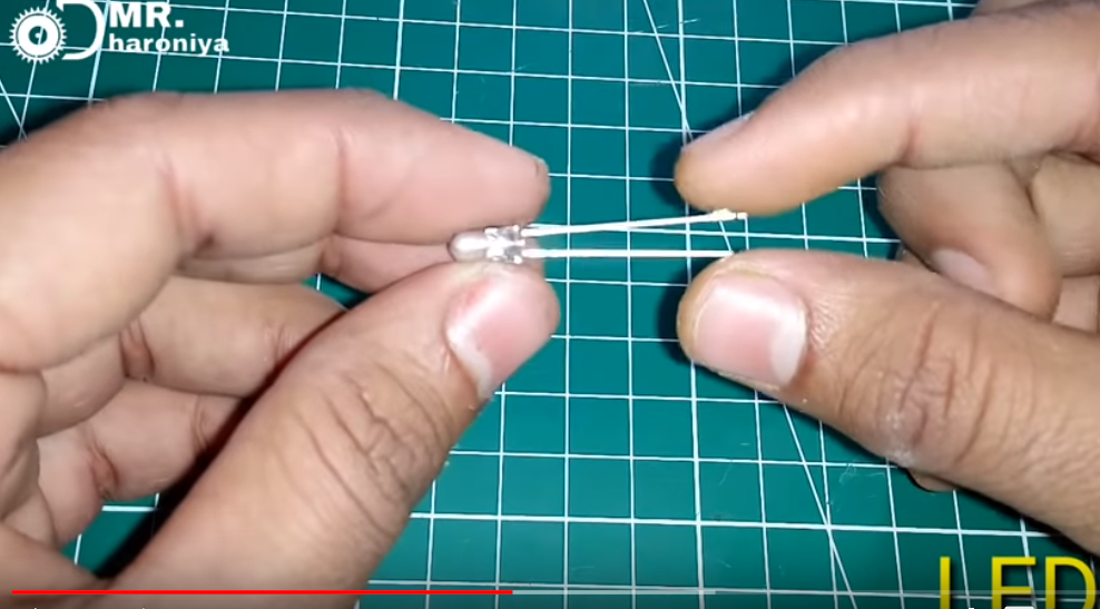
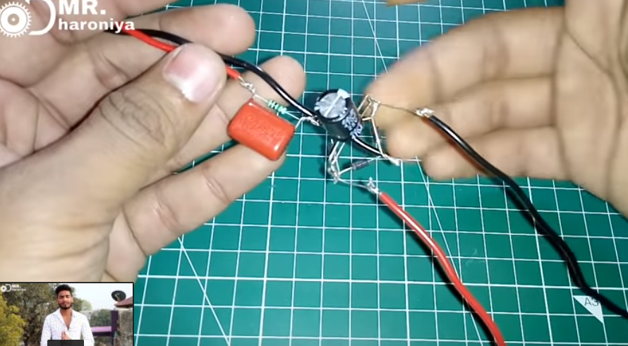
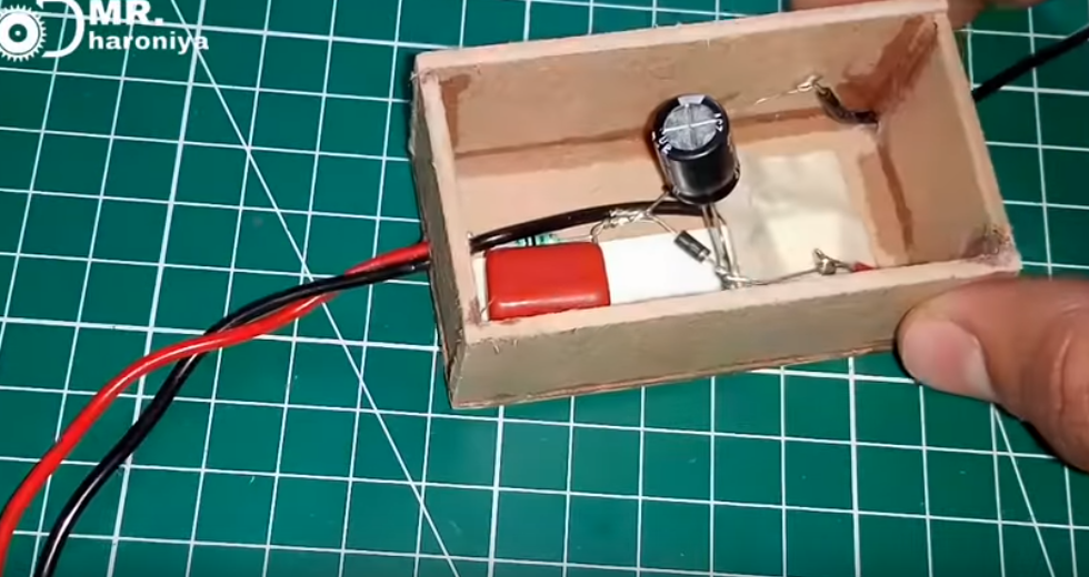
3.25v 470uf capacitor,zener diode 12v,led and solder them together.
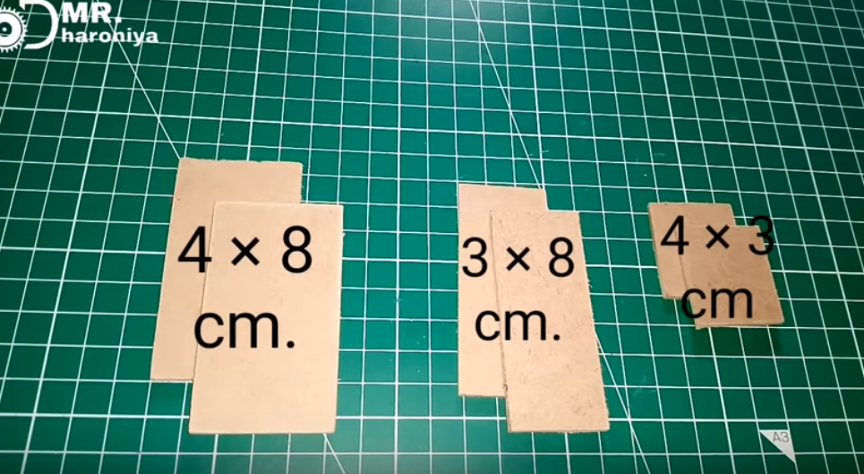
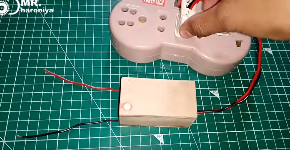
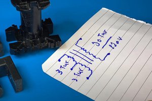
4. Prepare the paper boards, make a box and paste it in the box.

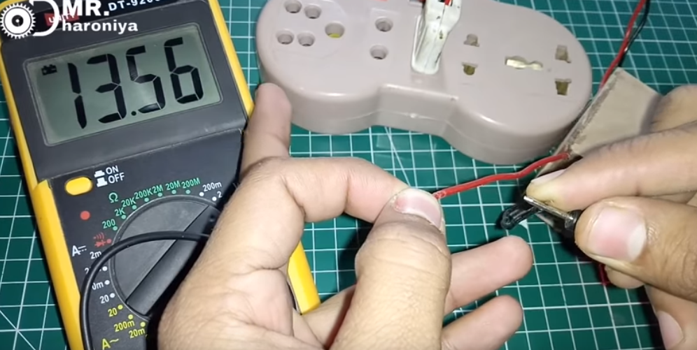
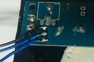
5. Finished and test.
6 Diagram circuit.
Product list:
IN4007 https://www.utsource.net/sch/IN4007
105J 400V https://www.utsource.net/sch/105J%20400V
1M ohm https://www.utsource.net/sch/1M%20ohm
25v 470uf capacitor https://www.utsource.net/sch/25v%20470uf%20capacitor
zener diode 12v https://www.utsource.net/sch/zener%20diode%2012v
led https://www.utsource.net/sch/led
1k ohm https://www.utsource.net/sch/1k%20ohm
More details, pls check the video on Youtube:


 utsourceproduct
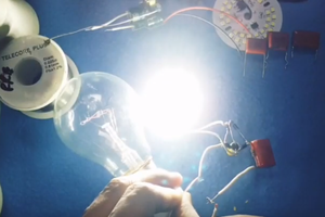
I think the design is innovative. Sometimes you just need 10mA @ 5VDC derived from the mains. How do you do it ? Do you get a Mains to 9VAC transformer & then implement the normal PSU design OR do you design/purchase a Mains to 5VDC converter. These options are expensive and bulky for just 10 mA @ 5VDC. So something cheap like this design is just the right thing perhaps. Might be inefficient but thats OK you are not using much power. This design does not generate noise (like a DC/DC converter) which is beneficial if you are powering some analog circuit with includes opamps, ADC's etc. Off course the open 220VAC nets are dangerous. Cover them with something & make it safe !