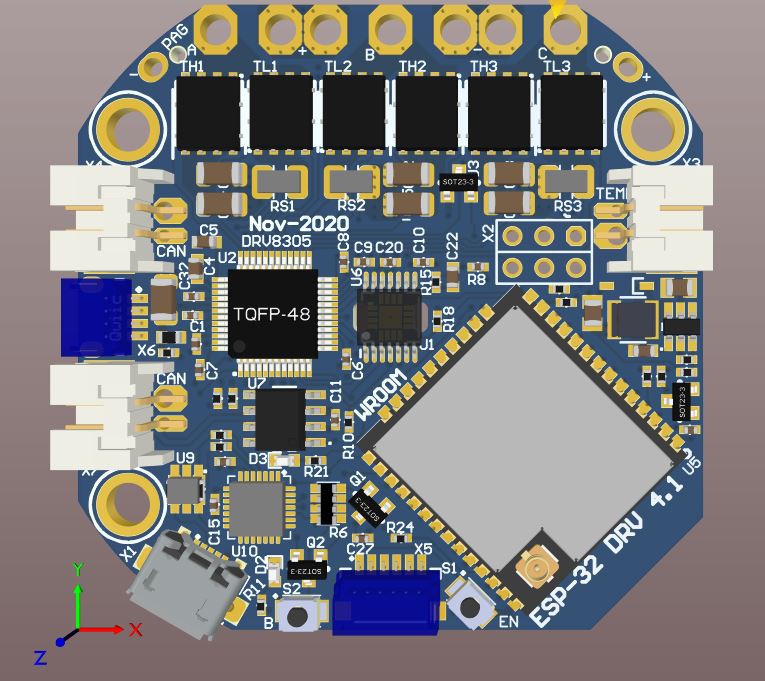
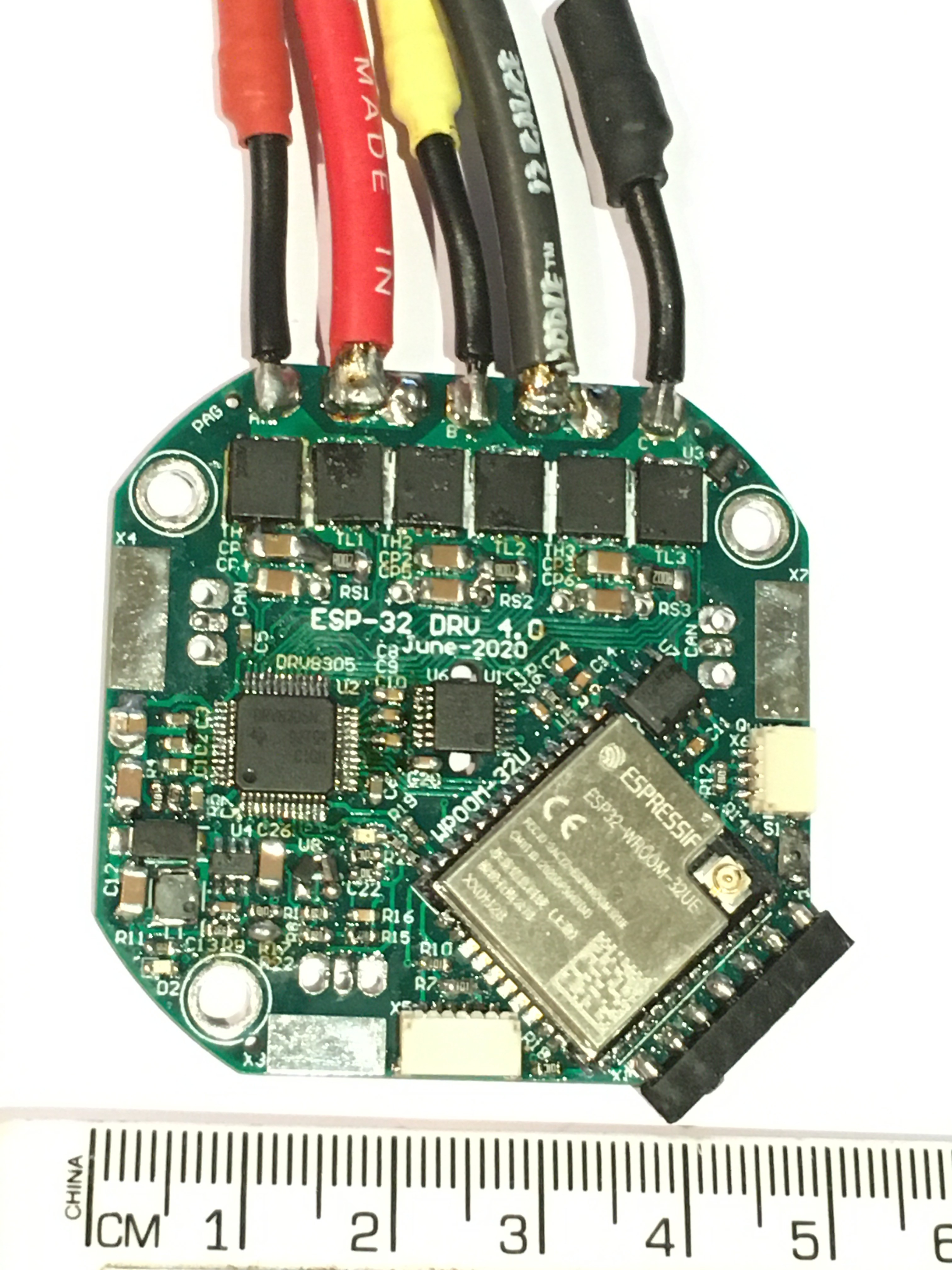
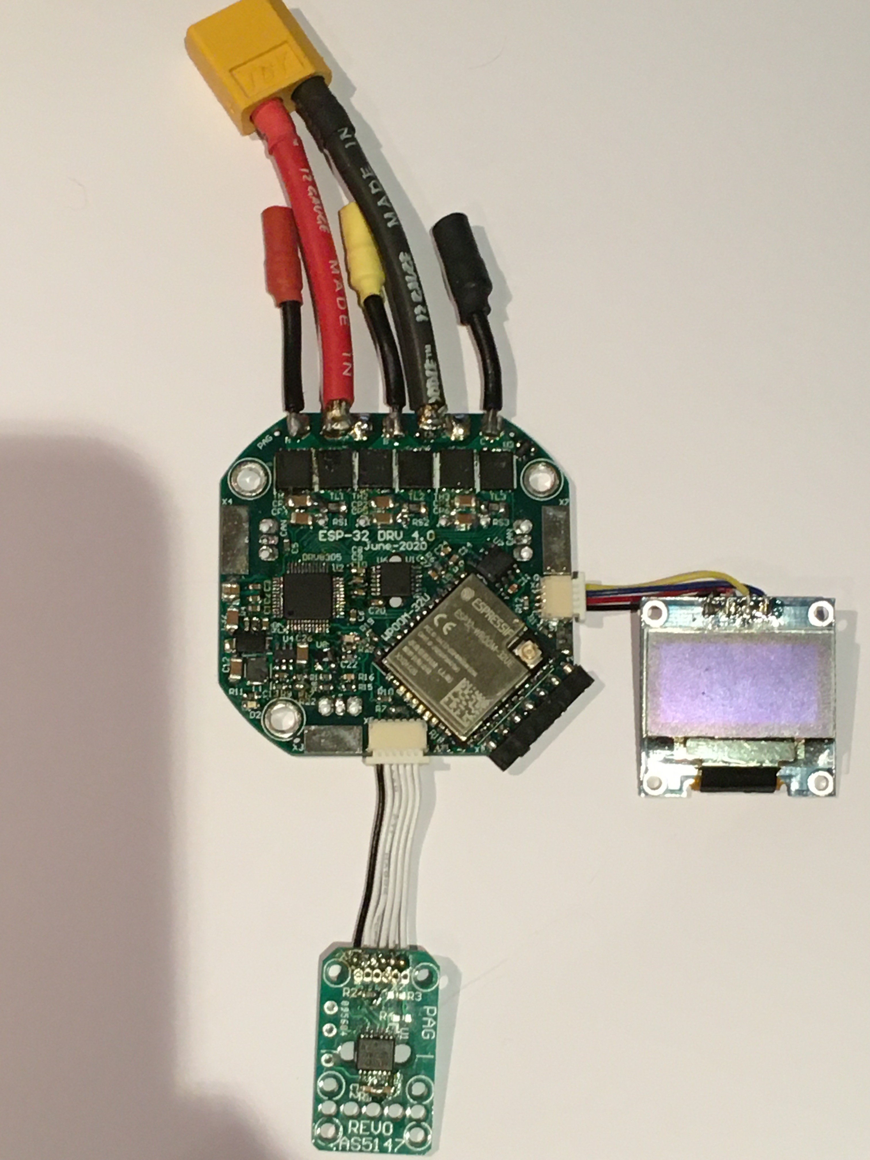
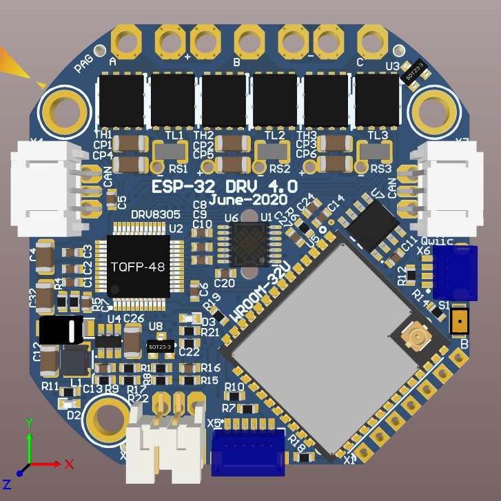
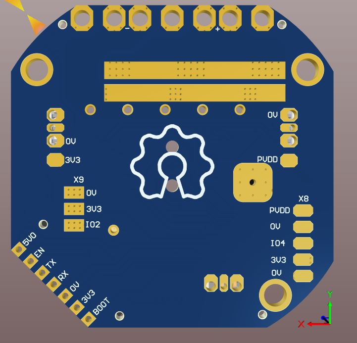
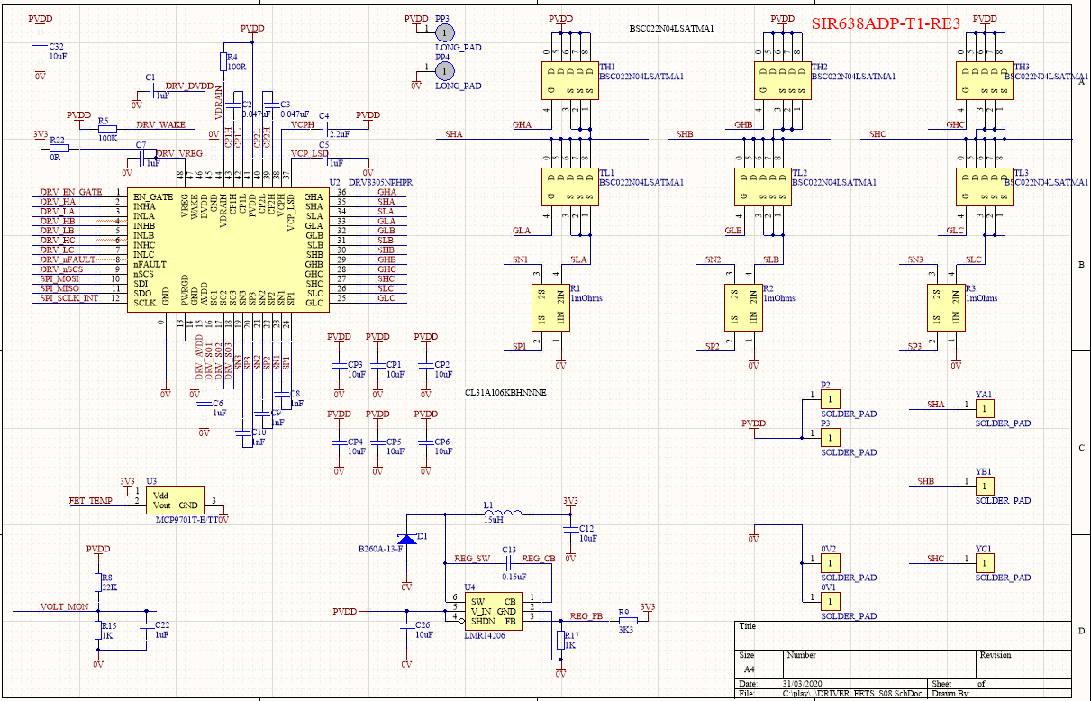
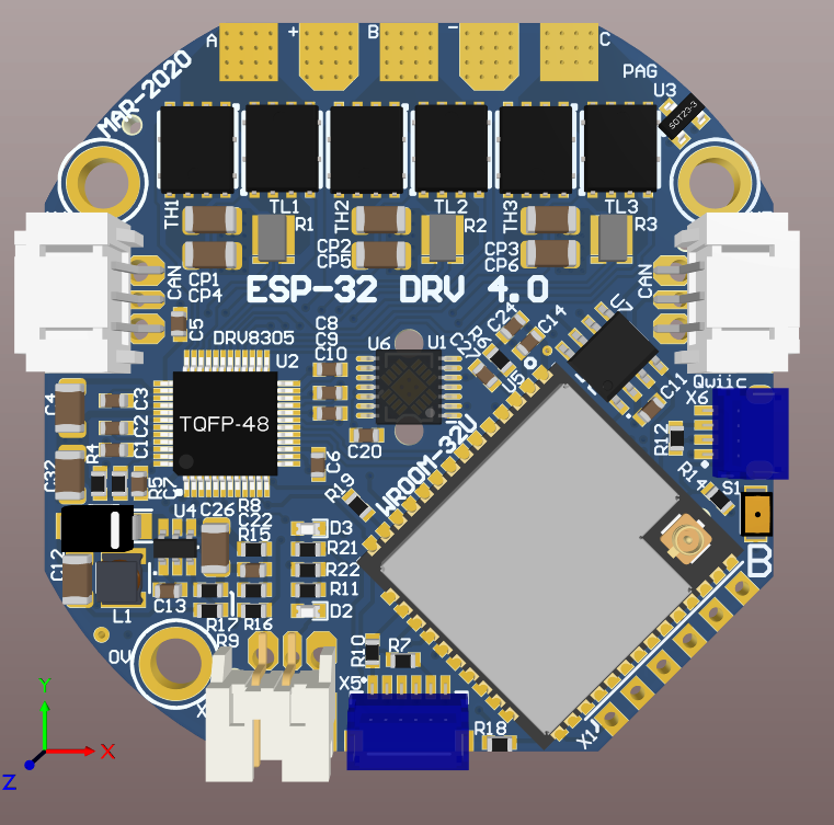
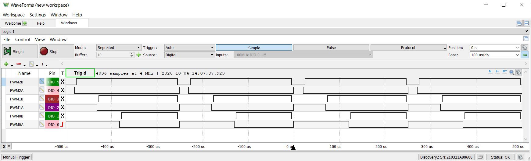
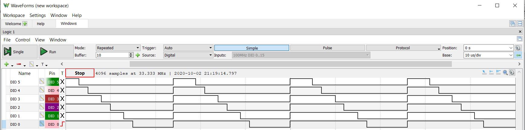
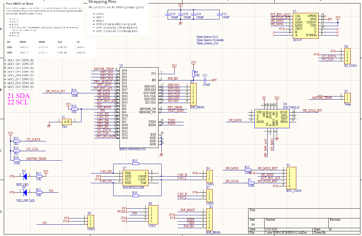
ESP-32 WROOM-32D has Three phase Centre Aligned MC-PWM, Dual SPI, I2C, 2MHz ADC, UART and CAN. Enough for a controller.
To make the experience fit your profile, pick a username and tell us what interests you.
We found and based on your interests.
Brushless ESP-32 REV0.pdfSchematicAdobe Portable Document Format - 1009.53 kB - 03/31/2020 at 08:01 |
|
|
Now with onboard USB for Arduino Programming and diagnostics. 30A @ 30V (~1kW)
Still helping u/_jeem_
Syncronising the start pulses
Half bridge MOSFET control and avoiding shoot through
PWMxA is the highside FET
PWMxB is the lowside FET
High = FET on
#include "driver/mcpwm.h"
#include "soc/mcpwm_reg.h"
#include "soc/mcpwm_struct.h"
#include "wiring_private.h" // pinPeripheral() function
// MCPWM Pins
#define GPIO_PWM0A_OUT 15 //Set GPIO 15 as PWM0A
#define GPIO_PWM0B_OUT 02 //Set GPIO 02 as PWM0B
#define GPIO_PWM1A_OUT 0 //Set GPIO 00 as PWM1A
#define GPIO_PWM1B_OUT 04 //Set GPIO 04 as PWM1B
#define GPIO_PWM2A_OUT 16 //Set GPIO 16 as PWM2A
#define GPIO_PWM2B_OUT 17 //Set GPIO 17 as PWM2B
static void setup_mcpwm_pins()
{
Serial.println("initializing mcpwm control gpio...n");
mcpwm_gpio_init(MCPWM_UNIT_0, MCPWM0A, GPIO_PWM0A_OUT);
mcpwm_gpio_init(MCPWM_UNIT_0, MCPWM0B, GPIO_PWM0B_OUT);
mcpwm_gpio_init(MCPWM_UNIT_0, MCPWM1A, GPIO_PWM1A_OUT);
mcpwm_gpio_init(MCPWM_UNIT_0, MCPWM1B, GPIO_PWM1B_OUT);
mcpwm_gpio_init(MCPWM_UNIT_0, MCPWM2A, GPIO_PWM2A_OUT);
mcpwm_gpio_init(MCPWM_UNIT_0, MCPWM2B, GPIO_PWM2B_OUT);
} // setup_pins()
static void setup_mcpwm()
{
setup_mcpwm_pins();
mcpwm_config_t pwm_config;
pwm_config.frequency = 4000; //frequency = 20000Hz
pwm_config.cmpr_a = 50.0; //duty cycle of PWMxA = 50.0%
pwm_config.cmpr_b = 50.0; //duty cycle of PWMxB = 50.0%
pwm_config.counter_mode = MCPWM_UP_COUNTER; //MCPWM_UP_DOWN_COUNTER; // Up-down counter (triangle wave)
pwm_config.duty_mode = MCPWM_DUTY_MODE_0; // Active HIGH
mcpwm_init(MCPWM_UNIT_0, MCPWM_TIMER_0, &pwm_config); //Configure PWM0A & PWM0B with above settings
mcpwm_init(MCPWM_UNIT_0, MCPWM_TIMER_1, &pwm_config); //Configure PWM0A & PWM0B with above settings
mcpwm_init(MCPWM_UNIT_0, MCPWM_TIMER_2, &pwm_config); //Configure PWM0A & PWM0B with above settings
mcpwm_deadtime_enable(MCPWM_UNIT_0, MCPWM_TIMER_0, MCPWM_ACTIVE_HIGH_COMPLIMENT_MODE, 40, 40);
mcpwm_deadtime_enable(MCPWM_UNIT_0, MCPWM_TIMER_1, MCPWM_ACTIVE_HIGH_COMPLIMENT_MODE, 40, 40);
mcpwm_deadtime_enable(MCPWM_UNIT_0, MCPWM_TIMER_2, MCPWM_ACTIVE_HIGH_COMPLIMENT_MODE, 40, 40);
mcpwm_sync_enable(MCPWM_UNIT_0, MCPWM_TIMER_0, MCPWM_SELECT_SYNC_INT0, 0);
mcpwm_sync_enable(MCPWM_UNIT_0, MCPWM_TIMER_1, MCPWM_SELECT_SYNC_INT0, 0);
mcpwm_sync_enable(MCPWM_UNIT_0, MCPWM_TIMER_2, MCPWM_SELECT_SYNC_INT0, 0);
MCPWM0.timer[0].sync.out_sel = 1;
delayMicroseconds(1000);
MCPWM0.timer[0].sync.out_sel = 0;
int pwm0 = 50;
int pwm1 = 30;
int pwm2 = 10;
mcpwm_set_duty(MCPWM_UNIT_0, MCPWM_TIMER_0, MCPWM_OPR_A, pwm0);
mcpwm_set_duty(MCPWM_UNIT_0, MCPWM_TIMER_0, MCPWM_OPR_B, pwm0);
mcpwm_set_duty(MCPWM_UNIT_0, MCPWM_TIMER_1, MCPWM_OPR_A, pwm1);
mcpwm_set_duty(MCPWM_UNIT_0, MCPWM_TIMER_1, MCPWM_OPR_B, pwm1);
mcpwm_set_duty(MCPWM_UNIT_0, MCPWM_TIMER_2, MCPWM_OPR_A, pwm2);
mcpwm_set_duty(MCPWM_UNIT_0, MCPWM_TIMER_2, MCPWM_OPR_B, pwm2);
} // setup_mcpwm
void setup() {
setup_mcpwm();
}
void loop() {
}
This is not ideal as I still have to set the duty cycle for both PWMxA and PWMxB and this could be prone to errors.
I would like to use PWMxA only
I thought that
MCPWM_ACTIVE_RED_FED_FROM_PWMXA
or
MCPWM_ACTIVE_RED_FED_FROM_PWMXB
would work correctly but it does not.
https://www.reddit.com/r/esp32/comments/j0lbrl/update_how_to_remove_delay_between_pwm_signals/
#include "driver/mcpwm.h"
#include "soc/mcpwm_reg.h"
#include "soc/mcpwm_struct.h"
#include "wiring_private.h" // pinPeripheral() function
// MCPWM Pins
#define GPIO_PWM0A_OUT 15 //Set GPIO 15 as PWM0A
#define GPIO_PWM0B_OUT 02 //Set GPIO 02 as PWM0B
#define GPIO_PWM1A_OUT 0 //Set GPIO 00 as PWM1A
#define GPIO_PWM1B_OUT 04 //Set GPIO 04 as PWM1B
#define GPIO_PWM2A_OUT 16 //Set GPIO 16 as PWM2A
#define GPIO_PWM2B_OUT 17 //Set GPIO 17 as PWM2B
static void setup_mcpwm_pins()
{
Serial.println("initializing mcpwm control gpio...n");
mcpwm_gpio_init(MCPWM_UNIT_0, MCPWM0A, GPIO_PWM0A_OUT);
mcpwm_gpio_init(MCPWM_UNIT_0, MCPWM0B, GPIO_PWM0B_OUT);
mcpwm_gpio_init(MCPWM_UNIT_0, MCPWM1A, GPIO_PWM1A_OUT);
mcpwm_gpio_init(MCPWM_UNIT_0, MCPWM1B, GPIO_PWM1B_OUT);
mcpwm_gpio_init(MCPWM_UNIT_0, MCPWM2A, GPIO_PWM2A_OUT);
mcpwm_gpio_init(MCPWM_UNIT_0, MCPWM2B, GPIO_PWM2B_OUT);
} // setup_pins()
static void setup_mcpwm()
{
setup_mcpwm_pins();
mcpwm_config_t pwm_config;
pwm_config.frequency = 40000; //frequency = 20000Hz
pwm_config.cmpr_a = 50.0; //duty cycle of PWMxA = 50.0%
pwm_config.cmpr_b = 50.0; //duty cycle of PWMxB = 50.0%
pwm_config.counter_mode = MCPWM_UP_COUNTER; //MCPWM_UP_DOWN_COUNTER; // Up-down counter (triangle wave)
pwm_config.duty_mode = MCPWM_DUTY_MODE_0; // Active HIGH
mcpwm_init(MCPWM_UNIT_0, MCPWM_TIMER_0, &pwm_config); //Configure PWM0A & PWM0B with above settings
mcpwm_init(MCPWM_UNIT_0, MCPWM_TIMER_1, &pwm_config); //Configure PWM0A & PWM0B with above settings
mcpwm_init(MCPWM_UNIT_0, MCPWM_TIMER_2, &pwm_config); //Configure PWM0A & PWM0B with above settings
mcpwm_sync_enable(MCPWM_UNIT_0, MCPWM_TIMER_0, MCPWM_SELECT_SYNC_INT0, 0);
mcpwm_sync_enable(MCPWM_UNIT_0, MCPWM_TIMER_1, MCPWM_SELECT_SYNC_INT0, 0);
mcpwm_sync_enable(MCPWM_UNIT_0, MCPWM_TIMER_2, MCPWM_SELECT_SYNC_INT0, 0);
MCPWM0.timer[0].sync.out_sel = 1;
delayMicroseconds(100);
MCPWM0.timer[0].sync.out_sel = 0;
mcpwm_set_duty(MCPWM_UNIT_0, MCPWM_TIMER_0, MCPWM_OPR_A, 70);
mcpwm_set_duty(MCPWM_UNIT_0, MCPWM_TIMER_0, MCPWM_OPR_B, 60);
mcpwm_set_duty(MCPWM_UNIT_0, MCPWM_TIMER_1, MCPWM_OPR_A, 50);
mcpwm_set_duty(MCPWM_UNIT_0, MCPWM_TIMER_1, MCPWM_OPR_B, 40);
mcpwm_set_duty(MCPWM_UNIT_0, MCPWM_TIMER_2, MCPWM_OPR_A, 30);
mcpwm_set_duty(MCPWM_UNIT_0, MCPWM_TIMER_2, MCPWM_OPR_B, 20);
} // setup_mcpwm
void setup() {
setup_mcpwm();
}
void loop() {
}
Boards can in from JLC PCB, components can in from LCSC and Mouser.
Hand populated the first one, testing as I went. I have a stencil for the next few.
A few little mistakes.
Programs via Arduino IDE using USB-TTL-3V3
I can control a motor and a joint's position via bluetooth and display into on the I2C OLED (FET Temp, Battery Voltage, Joint Position, Motor current).
Has two absolute magnetic encoders, for for motor position and one for joint position
I do not recommend Bluetooth/wifi for joint control.
CAN is also up and running.
Connectors clockwise from the top
Connectors on the back
PDF in files
The standard SPI Transfer code does tot work well in an IRQ mainly becaise it is run out of FLASH. Uese the IRAM_ATTR to put it in RAM.
Other digitalWrte() is slow and should not be uses in the IRQ.
Use GPIO.out_w1ts = ((uint32_t)1 << IO_PIN_Number); to set the pin high
Use GPIO.out_w1ts = ((uint32_t)1 << IO_PIN_Number); to set the pin low
This can only be used when the IO_PIN_Number is 0-31
There is other code for 32-39 pins.
SPI Set-up
#include "driver/periph_ctrl.h"
#include "driver/spi_master.h"
#include "soc/gpio_sig_map.h"
#include "soc/spi_reg.h"
#include "soc/dport_reg.h"
#include "soc/spi_struct.h"
static const int spiClk = 4000000; // 1 MHz
SPIClass * hspi = NULL;
void IRAM_ATTR SPIInit(void)
{
hspi = new SPIClass(HSPI);
hspi->begin();
pinMode(INT_ENC_nCS, OUTPUT);
pinMode(EXT_ENC_nCS, OUTPUT);
pinMode(DRV_nSCS, OUTPUT);
GPIO.out_w1ts = ((uint32_t)1 << INT_ENC_nCS);
GPIO.out_w1ts = ((uint32_t)1 << EXT_ENC_nCS);
GPIO.out_w1ts = ((uint32_t)1 << DRV_nSCS);
hspi->beginTransaction(SPISettings(spiClk, MSBFIRST, SPI_MODE1));
SPI2.mosi_dlen.usr_mosi_dbitlen = (1 * 16) - 1;
SPI2.miso_dlen.usr_miso_dbitlen = (1 * 16) - 1;
}
void IRAM_ATTR SPI_Read_Encoder(){
GPIO.out_w1tc = ((uint32_t)1 << INT_ENC_nCS);
SPI2.data_buf[0] = 0xFFFF;
SPI2.cmd.usr = 1;
while(SPI2.cmd.usr);
GPIO.out_w1ts = ((uint32_t)1 << INT_ENC_nCS);
encoder_int = SPI2.data_buf[0] & 0xFFFF;
if(!SPI2.ctrl.rd_bit_order){
encoder_int = (encoder_int >> 8) | (encoder_int << 8);
}
encoder_int = encoder_int & 0x3FFF ;
}
The standard Libraries for Arduino by Espressif are very limiting. Previously I had to fix the Sync Function. Now the problem is Frequency, resolution and updating the duty cycle in an interrupt. There is an argument to make on getting the interrupt sub-routine very short. All of my motor commutation code (and SPI reads) are within an 5KHz timer. It consumes 5-10% CPU time. By default the Arduino code runs out of FLASH and running FLASH code in an interrupt causes problems (more info on why is needed).
MCPWM Initialization code
#define TIMER_CLK_PRESCALE 1
#define MCPWM_CLK_PRESCALE 0
#define MCPWM_PERIOD_PRESCALE 4
#define MCPWM_PERIOD_PERIOD 2048
static void IRAM_ATTR setup_mcpwm()
{
setup_mcpwm_pins();
mcpwm_config_t pwm_config;
pwm_config.frequency = 4000000; //frequency = 20000Hz
pwm_config.cmpr_a = 0; //duty cycle of PWMxA = 50.0%
pwm_config.cmpr_b = 0; //duty cycle of PWMxB = 50.0%
pwm_config.counter_mode = MCPWM_UP_DOWN_COUNTER; // Up-down counter (triangle wave)
pwm_config.duty_mode = MCPWM_DUTY_MODE_0; // Active HIGH
mcpwm_init(MCPWM_UNIT_0, MCPWM_TIMER_0, &pwm_config); //Configure PWM0A & PWM0B with above settings
mcpwm_init(MCPWM_UNIT_0, MCPWM_TIMER_1, &pwm_config); //Configure PWM0A & PWM0B with above settings
mcpwm_init(MCPWM_UNIT_0, MCPWM_TIMER_2, &pwm_config); //Configure PWM0A & PWM0B with above settings
Serial.print("clk_cfg.prescale = ");
Serial.println( MCPWM0.clk_cfg.prescale);
Serial.print("timer[0].period.prescale = ");
Serial.println( MCPWM0.timer[0].period.prescale);
Serial.print("timer[0].period.period = ");
Serial.println( MCPWM0.timer[0].period.period);
Serial.print("timer[0].period.upmethod = ");
Serial.println( MCPWM0.timer[0].period.upmethod);
mcpwm_stop(MCPWM_UNIT_0, MCPWM_TIMER_0);
mcpwm_stop(MCPWM_UNIT_0, MCPWM_TIMER_1);
mcpwm_stop(MCPWM_UNIT_0, MCPWM_TIMER_2);
MCPWM0.clk_cfg.prescale = MCPWM_CLK_PRESCALE;
MCPWM0.timer[0].period.prescale = MCPWM_PERIOD_PRESCALE;
MCPWM0.timer[1].period.prescale = MCPWM_PERIOD_PRESCALE;
MCPWM0.timer[2].period.prescale = MCPWM_PERIOD_PRESCALE;
delay(1);
MCPWM0.timer[0].period.period = MCPWM_PERIOD_PERIOD;
MCPWM0.timer[1].period.period = MCPWM_PERIOD_PERIOD;
MCPWM0.timer[2].period.period = MCPWM_PERIOD_PERIOD;
delay(1);
MCPWM0.timer[0].period.upmethod =0;
MCPWM0.timer[1].period.upmethod =0;
MCPWM0.timer[2].period.upmethod =0;
delay(1);
Serial.print("clk_cfg.prescale = ");
Serial.println( MCPWM0.clk_cfg.prescale);
Serial.print("timer[0].period.prescale = ");
Serial.println( MCPWM0.timer[0].period.prescale);
Serial.print("timer[0].period.period = ");
Serial.println( MCPWM0.timer[0].period.period);
mcpwm_start(MCPWM_UNIT_0, MCPWM_TIMER_0);
mcpwm_start(MCPWM_UNIT_0, MCPWM_TIMER_1);
mcpwm_start(MCPWM_UNIT_0, MCPWM_TIMER_2);
mcpwm_sync_enable(MCPWM_UNIT_0, MCPWM_TIMER_0, MCPWM_SELECT_SYNC_INT0, 0);
mcpwm_sync_enable(MCPWM_UNIT_0, MCPWM_TIMER_1, MCPWM_SELECT_SYNC_INT0, 0);
mcpwm_sync_enable(MCPWM_UNIT_0, MCPWM_TIMER_2, MCPWM_SELECT_SYNC_INT0, 0);
delayMicroseconds(1000);
MCPWM0.timer[0].sync.out_sel = 1;
delayMicroseconds(1000);
MCPWM0.timer[0].sync.out_sel = 0;
} // setup_mcpwm
Some rules
STOP MCPWM before period, etc update
START MCPWM before SYNC
Delay long enough for at least one period before disabling sync .
Use IRAM_ATTR to change the code from FLASH based to RAM based for putting into the Interrupt
void IRAM_ATTR Three_Phases(void)
{
if (Motor_on==0)
{
PWMUU = 0;
PWMVV = 0;
PWMWW = 0;
}
MCPWM0.channel[0].cmpr_value[MCPWM_OPR_A].cmpr_val = PWMUU;
MCPWM0.channel[1].cmpr_value[MCPWM_OPR_A].cmpr_val = PWMVV;
MCPWM0.channel[2].cmpr_value[MCPWM_OPR_A].cmpr_val = PWMWW;
}
Because MCPWM0.timer[2].period.upmethod =0; is instant update this code update Duty cycle right away.
May have to check for glitches or change upmethod to start of period.
Create an account to leave a comment. Already have an account? Log In.
How close is you're current design to the PDF you have uploaded?
You're using DRV8305 in your design. The MIT Mini Cheetah uses the DRV8323. They seem to have very similar specs other than the voltage ranges, which don't really matter much. Are these basically almost the same chip thus it doesn't matter much? The price seems to be around $5 on Digikey for DRV8305 and $4 for DRV8323, so just based on price seems like DRV8305 has more features/is newer?
DRV8305 is available on JLCPCB assembly service. DRV8323RH is a better Chip. Less external components with integrated Buck and less/better connections and routing to FETs. 8323 uses less PCB area. I have been designing a mini 10-20A ESP-32 WROOM controller about the 8323RH. Will also make a prototype soonish.
Looks like JLCPCB now has DRV8323 listed in their SMT parts library. I don't recall seeing it listed there before.
Any chance you might be up for releasing the board files for this? I'm really interested in it.
Good timing. I have been working on fixing/improving this design for the past week. Check out the latest update. Once do a new prototype and get it working, I'll release the files. I'm hoping you can just order them directly from JLCPCB.
Sweet! The update looks awesome. Can't wait to order my own from JLCPCB since I've been wanting to use their SMT assembly service.
BTW, just bought a couple of low KV 50mm diameter brushless motors https://www.aliexpress.com/item/4000734710615.html to test with. They're pretty cheap at $17 with shipping, but seem to have similar kv and size to your Multistar 5010 motors. If your latest design is 30A at 30V then these seem to have the right specs.
@John Lauer Those motors aren't great (sorry). Most brushless motors state the dimensions of the stator 50mm dia and 10 mm high. Those motors state the dimensions of the bell. Also the magnets are thin and not curved. These are the same as flycat in the following link. http://build-its-inprogress.blogspot.com/2016/01/motor-characterization-for-small.html
I use https://gogo-rc.com/store/index.php?route=product/product&product_id=3493
Ok, gotcha. That blog post was a great find. I cancelled that order and got your suggestion instead. I also ordered a couple 4112 and 3508 motors from the same brand as well because I may need to make some smaller actuators too. https://www.aliexpress.com/item/32490567876.html and https://www.aliexpress.com/item/32509216587.html
Great Project , thank you for sharing. I'm fascinating to see how technologies is just being democratize and how you realise project that seems to be unfeasible, may be 10 years ago for, by just one person! Congratulations !
Would it be possible to use digital encoder using RS485 communication protocol ?
Are you still planing to share sources (BOM, Schématics, PCB, etc...)?
Thank you again and kinds regards
Hey Paul, I'm trying to do something similar with an ESP32, an L293 driver, an AMT103 encoder, a tiny brushless motor and the Arduino IDE. I have successfully controlled the position of the motor with an Arduino Uno but I am having problems with the ESP, I think the problem is syncing the PWM signals with the ESP32. I saw you found a problem with the MCPWM.h file and I fixed mine but I still don't get phase-corrected PWM signals. I tried with your example codes but have had no luck. Do you have any advice or have you found anything new to do so? Thanks you!
I've made something similar. The ESP has normally some serious timing issues.
You should look the Video of Andreas Spiess..
Because of that I am using a Teensy 3.2 and modulating a sine wave for a asynchron motor.
200kHz interrupt routine is working fine...
Probably it works with the right code... : /
It took alot of work to get the code to work. The examples work fine for me. It could have been a different version of the drivers/libraries. I will try it with the new Arduino build and let you know.
I got it working. I tried with a fresh install and added the lines needed in the MCPWM.h file. Thanks for your help and for sharing your findings!
Maybe the SwarmDrive code could help you. Have a look at swarmdrive.nickstick.nl
Nice project. What is the update rate? How are you doing back emf?
@Paul Gould if you mean the timer interval, it can be set. But the SwarmDrive firmware on GitHub is just a starting point for users of the board (my hopes are that people will improve the code and work on different strategies). Currently I'm not using bemf (although the board has a sense with resistor broken out). I use the AS5048b for my commutation logic, but I still have many things to explore.
Amazing work, would really like to see more! Got stuck on mine with the part selection, are you planning on sharing your PCB files and BOM?
I've added the Schematic as a PDF. I will open source the files after I've made a prototype and proved that it works.
Become a member to follow this project and never miss any updates
Hi Paul, looks great! I love that low cost WiFi enabled controllers plus solid state encoders and low cost out runners are finally intersecting. Exciting time for medium performance smallish robotics.
I'd love to build one of these for an application I'm working on, are you still planning to release the PCBA files?