 M. Bindhammer
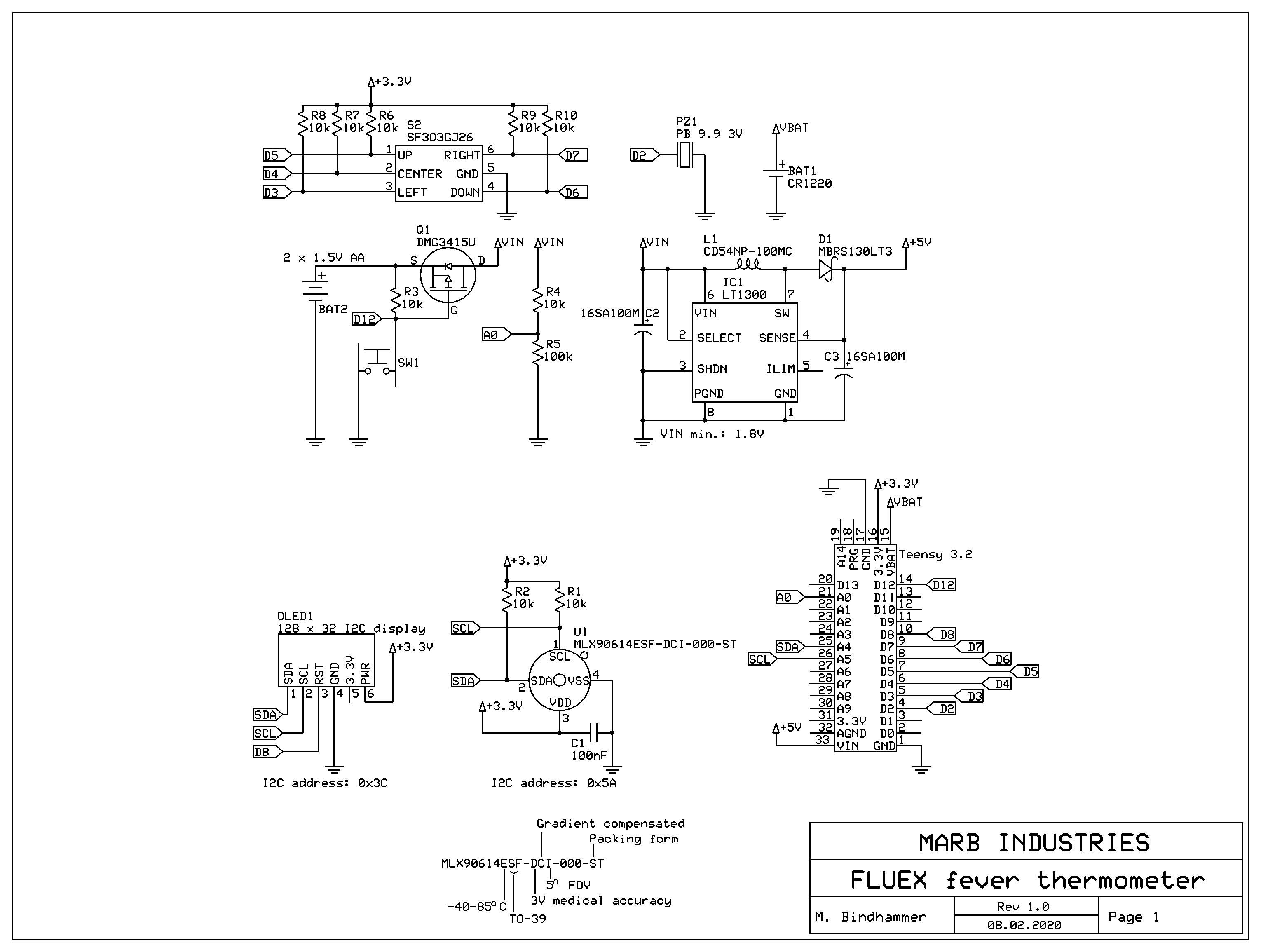
As usual I start with the creation of the schematic for a project. As already mentioned that the circuit is powered by two 1.5 V alkaline batteries. The LT1300 forms with L1, D1, C2 and C3 a 5V step-up converter. The 5V output voltage is guaranteed to a minimum input voltage of 1.8V. The 5V are then feeded into the Teensy.
Q1, R3 and SW1 form a simple latching style power circuit. On power up the R3 resistor pulls up the gate on the U1 p-channel mosfet which prevents current from flowing through U1. When the user presses SW1, the gate on U1 gets pulled to ground which allows the current to flow, the LT1300 and the Teensy turn on. The Teensy then drives the GPIO pin to ground. When the user releases SW1 the GPIO pin keeps the gate low. The Teensy (or user) then just Hi-Zs the GPIO pin when it needs to shutdown. This way it can make sure the data is safe when it shuts down.
Resistors R4 and R5 are wired as voltage divider to monitor the battery voltage. R1 and R2 are pullup resistors for the I2C bus, R6 to R10 are pullup resistors for the miniature joystick. PZ1 serves as an acoustic signal generator. BAT1 feeds the internal RTC of the Teensy. For this purpose a 32.768 kHz crystal must be soldered to the bottom of the Teensy board, for details see here.
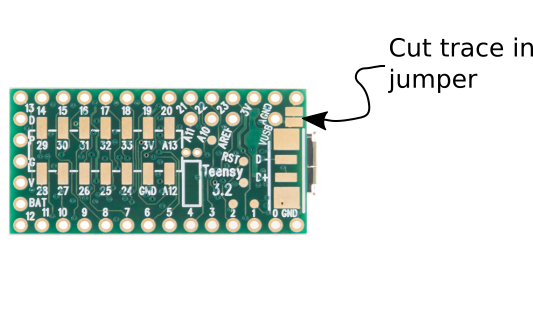
Since we're going to be powereing the Teensy from the 5V step-up converter, we want to cut the jumper that bridges the USB bus voltage to the Teensy power input.
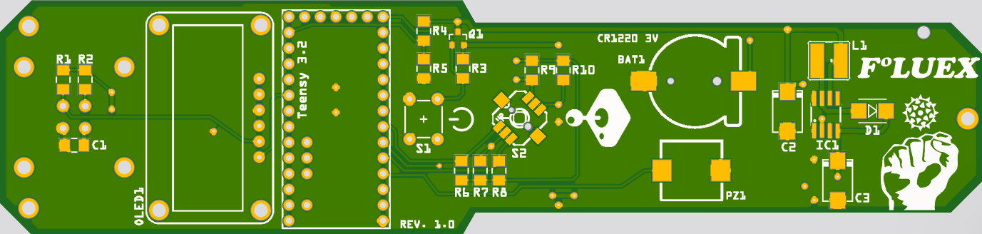
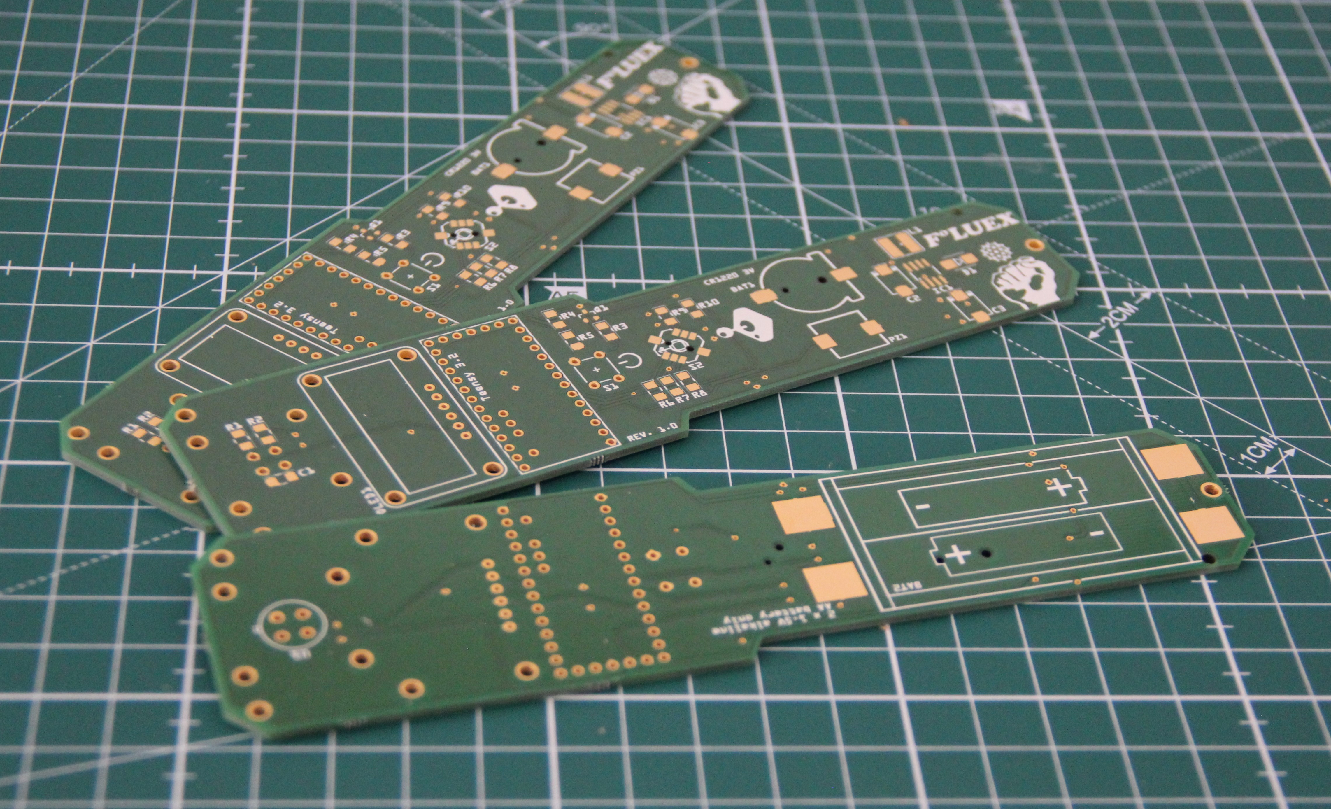
I designed the PCB layout with Fritzing. The board has a custom shape. For this I used Inkscape - an excellent tutorial can be found here. As usual I routed the PCB by hand. And as usual I am using AISLER to manufacture the board. They are quick, cheap and very reliable.
Top layer rendering:
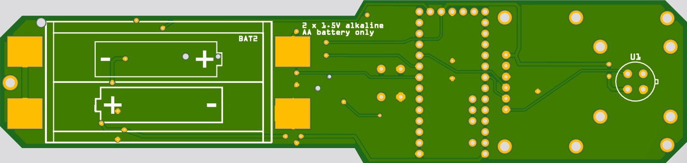
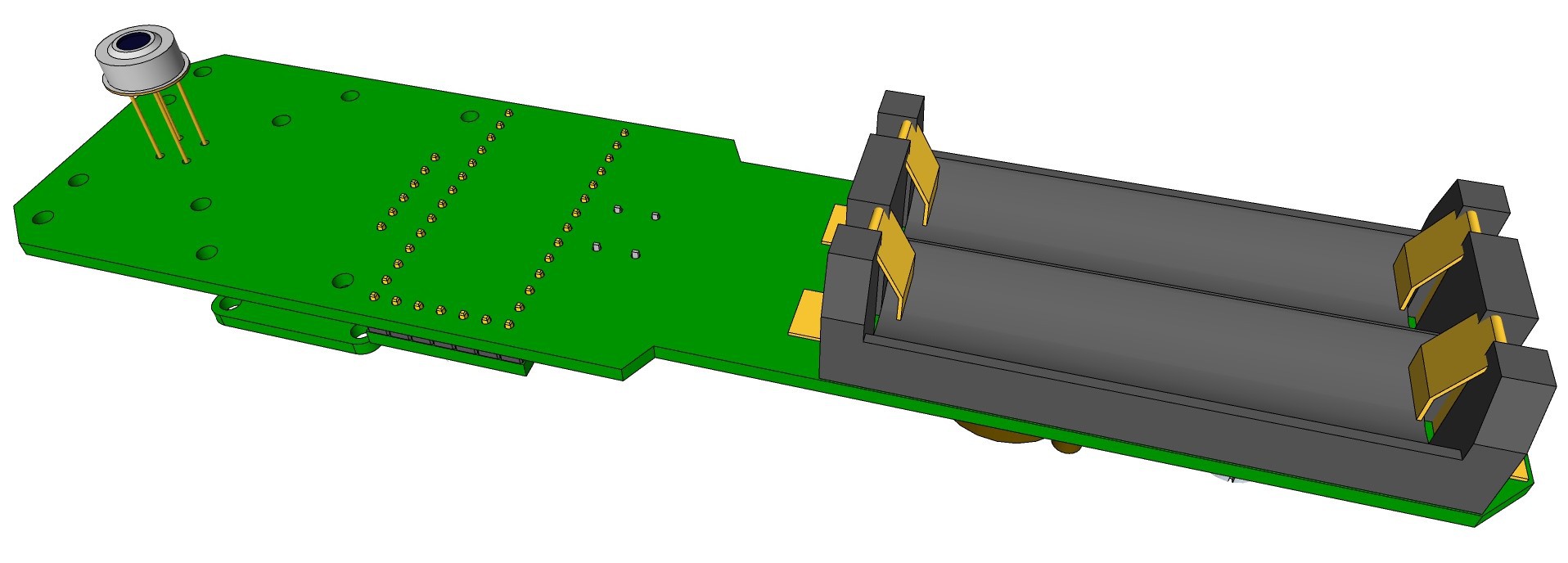
Bottom layer rendering:
 Before the housing can be designed, a 3-D model of the populated board is required. I use Sketchup for 3-D modeling. Fritzing is not able to generate a 3-D rendering of the board, so I had to draw everything by hand again, using dimensional drawings and data sheets of the components.
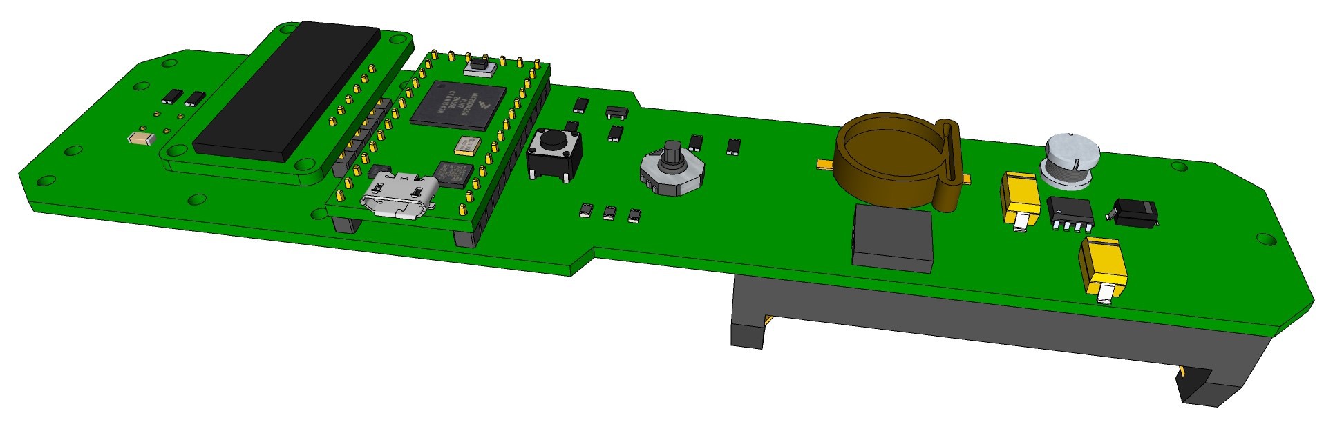
 I won't reflow the board, just hand solder the few SMD components. For SMD soldering it is important to use a lot of flux (flux pen). Flux residues can be easily removed with 100% ethanol and an old toothbrush after soldering.
 Populated top side (just the infrared Thermometer is missing - back order):
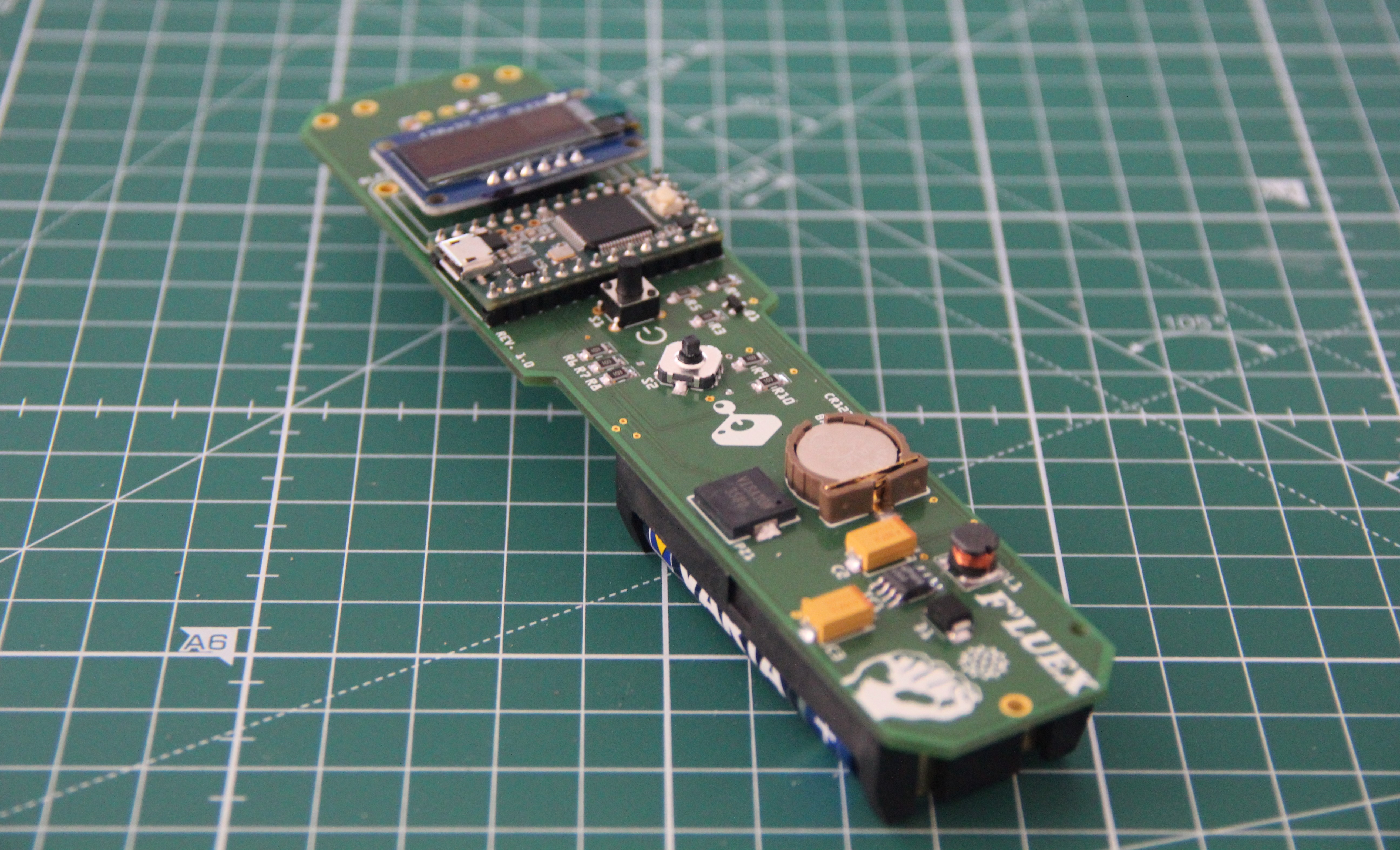
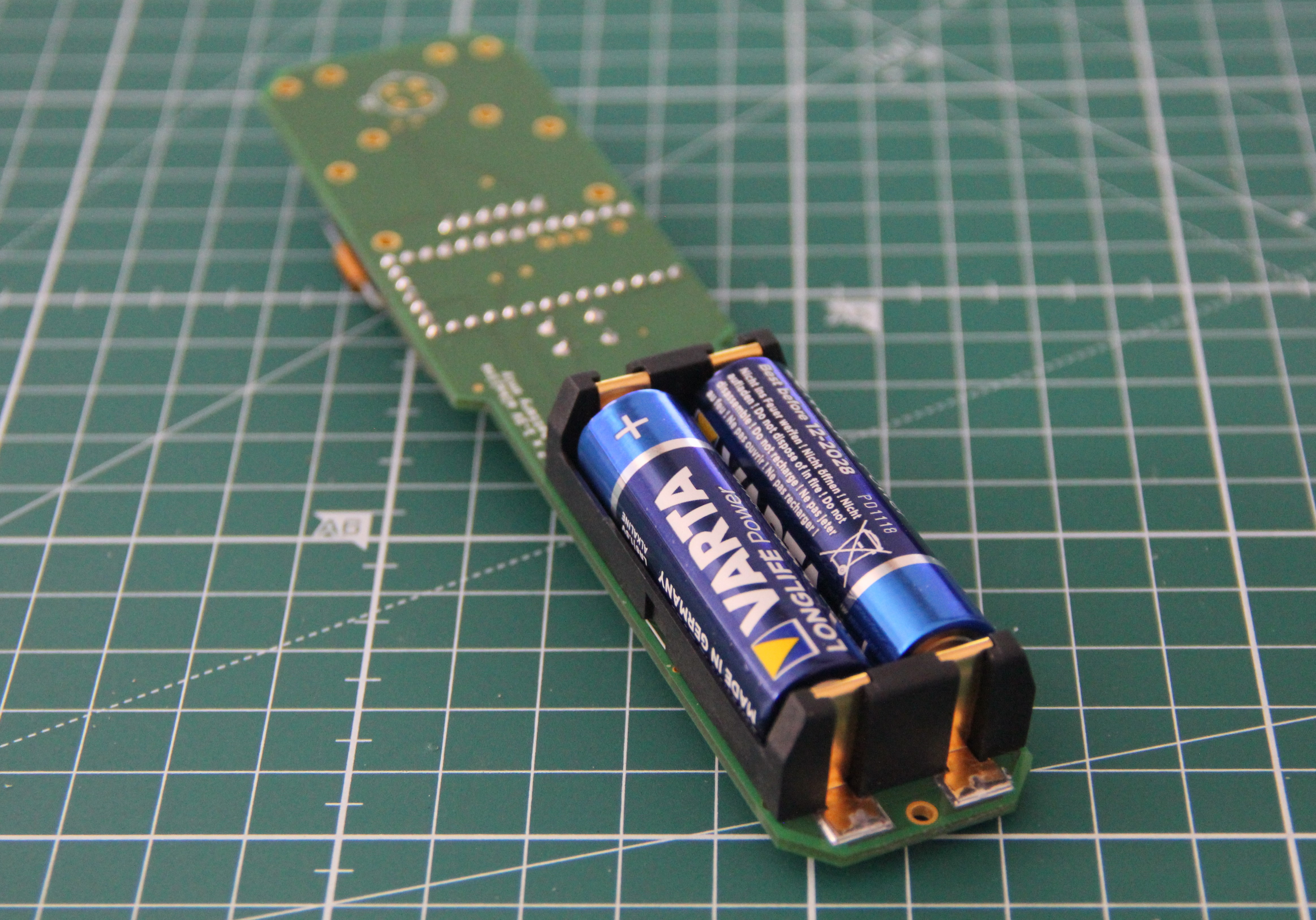
Populated bottom side:
Discussions
Become a Hackaday.io Member
Create an account to leave a comment. Already have an account? Log In.