 Tim
TimThanks to express shipping, the populated PCBs arrived less then a week after ordering them. A top down photo of one ALU board with 4 bitslices is shown below.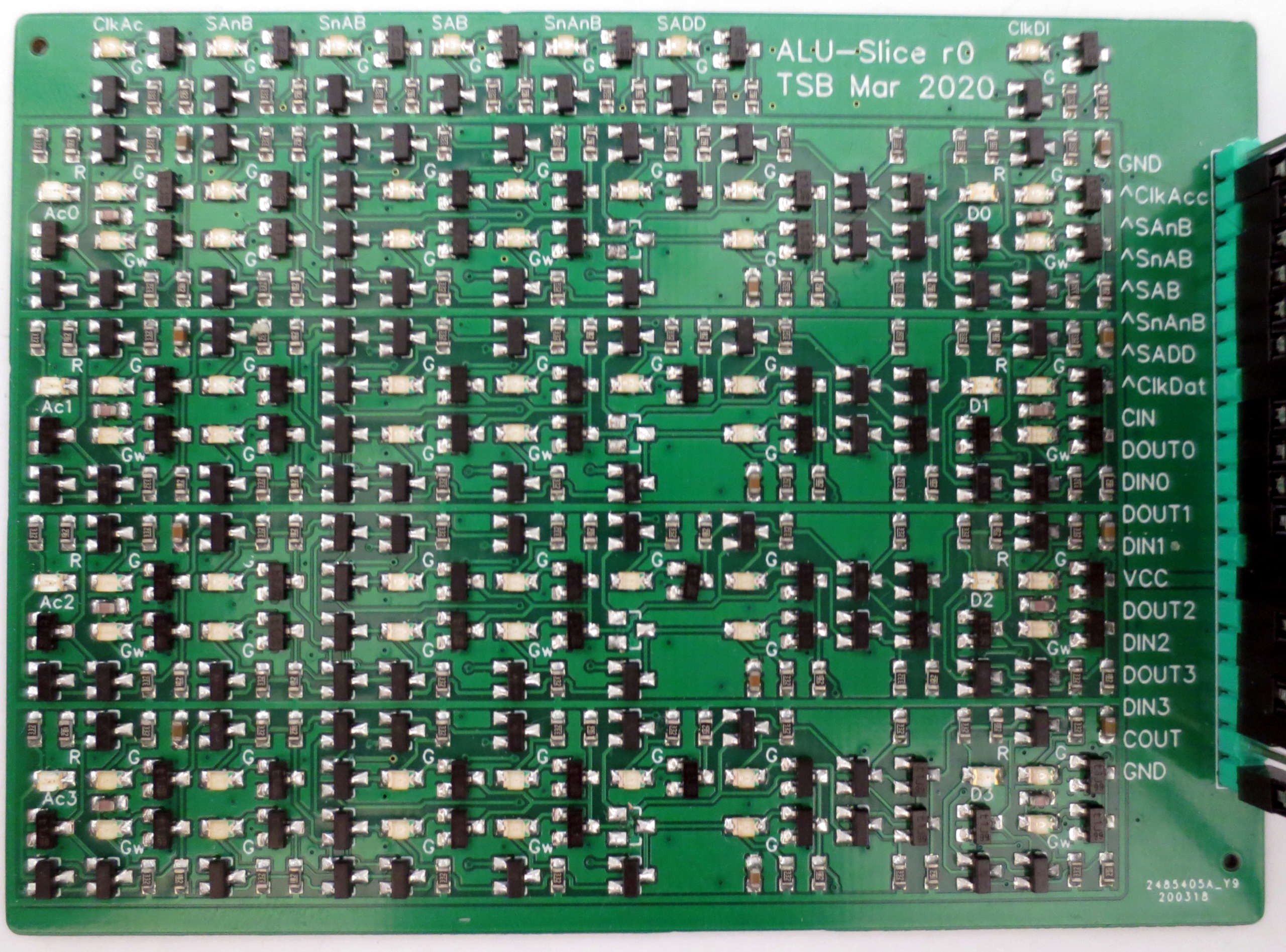 The dual-input diodes for the boolean unit multiplexer line up neatly in one row.
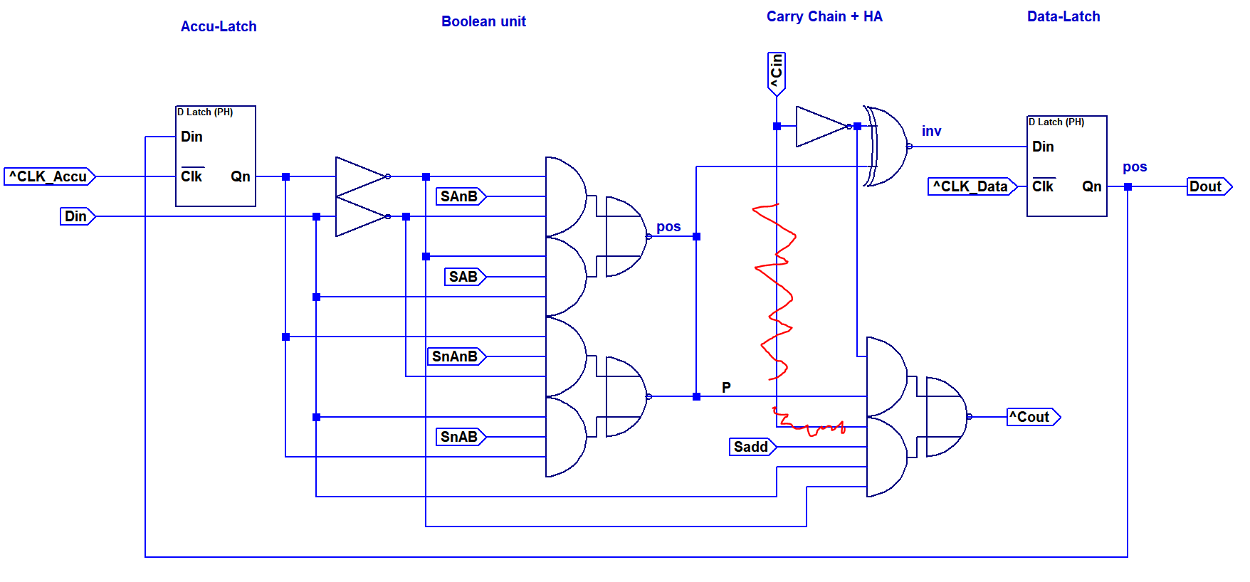
 I tested the board using an ATMega168 to generate stimulus signals. Unfortunately, I found a small mistake I made earlier in the design: The generate term in the carry chain should not have an additional carry input, see below. Luckily it was easily possible to fix this by removing one diode per slice from the board. You can see the unpopulated pads in the center of the top down image.
Removing this signal would have allowed to densify the layout significantly and also add the carry-chain inverter to the output, so the carry signal is non-inverting. But well, next time...
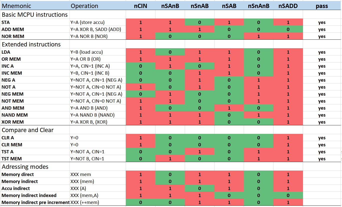
 The list below shows the control signal configurations that were tested. Only the first three cases apply to operations that are used by the MCPU ISA. In addition, Y=B is needed for address loading.
The other operations would allow for a later extension of the instruction set.
Clockspeed was tested up to 2 MHz. Even for the worst case (ADD with carry in=1), the signal integrity looked excellent, suggesting that also 4 MHz and higher may pass. One limitation seems to be in the pull-up capability of the clock driver with a fan-out of 8. It may be a good idea to reduce the collector resistor on high fan-out drivers or to design a push-pull driver.
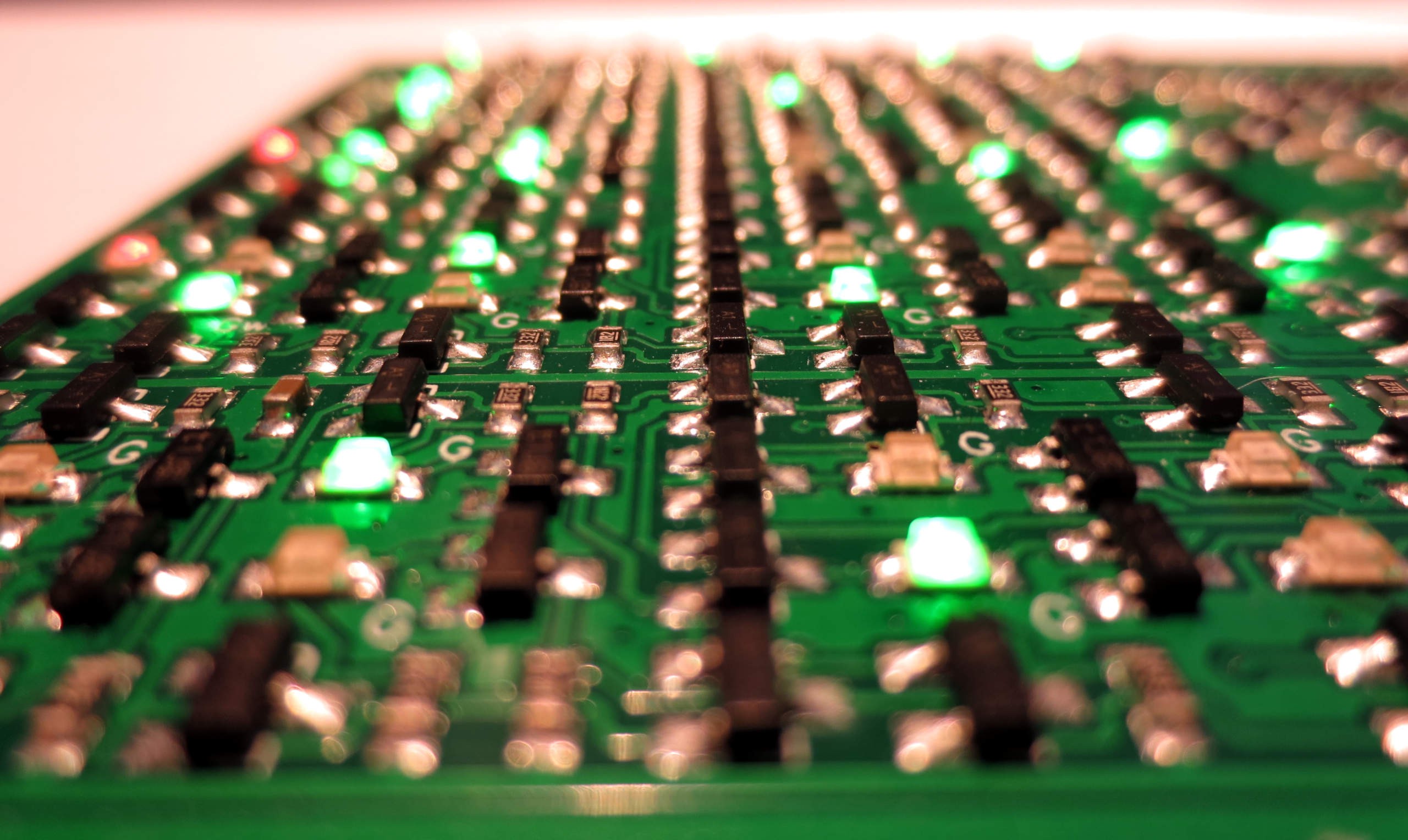
 Finally, the ALU board in action, repeating a sequence of ADD A,3 and NEG A:
Discussions
Become a Hackaday.io Member
Create an account to leave a comment. Already have an account? Log In.
I'm looking forward to seeing the next logs !!!
Are you sure? yes | no