 Tim
Tim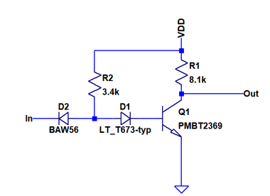
Replacing the base diodes in an DTL gate with an LED saves one component. One very interesting side effect is that the LED also emits light. Modern LEDs are already quite bright at around 1mA of current, so the normal base current will be sufficient to turn it on.
But what is the impact on the circuit behavior? Usually we would like to use fast switching diodes for any logic circuit. Switching diodes are optimized for low capacitance and low recovery time to be able to switch very fast between forward and reverse operation. Here I am using a BAW56 dual diode, which has a capacitance of 2pF and 6ns reverse recovery time, as the input diode. LEDs are not optimized for switching operation. They typically have a fairly high capacitance of around ~40pF and take long time to be switched off. Therefore, using an LED in place of D2, the input diode, would slow down the gate significantly.
The base diode is, however, never in reverse operation. Therefore the bad switching properties of the LED are not an issue. In addition, the higher capacitance helps to pull down the base potential quicker if the transistor is to be turned off. You sometimes see intentional reach-through capacitors in parallel to the base diode in DTL gates.
Some attention has to be paid to the terminal between D1 and Q1 base. If the transistor is turned off, this terminal is pulled to negative voltage and is basically floating, since the base-emitter diode is reverse biased. I found that this can lead to a shift of switching voltage depending on duty cycle and frequency of the incoming signal. It may be advised to use a bleeder resistor to conntect this node to the ground. Due to simplicity, I omitted this and made sure to design glitch free logic instead...
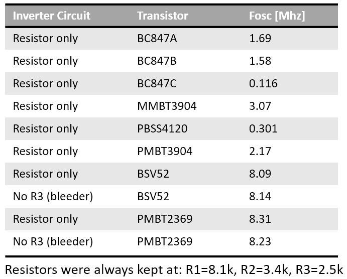
I spent quite some time optimizing the basic gate in LTspice. To measure switching speed, I simulated a 5 stage ring oscillator. One crucial choice was to pick the right transistor, as I also outlined in greater detail here.
You can see simulation results for several different configurations above. I also tried various configurations with reach through caps and baker clamps but found that chosing the right transistor, the PMBT2369, yielded much better results that all other options. The PMBT2369 is available in a SOT23 SMD package for around $0.02, so there is really no reason to use the BC847 or MMBT3904 over it.
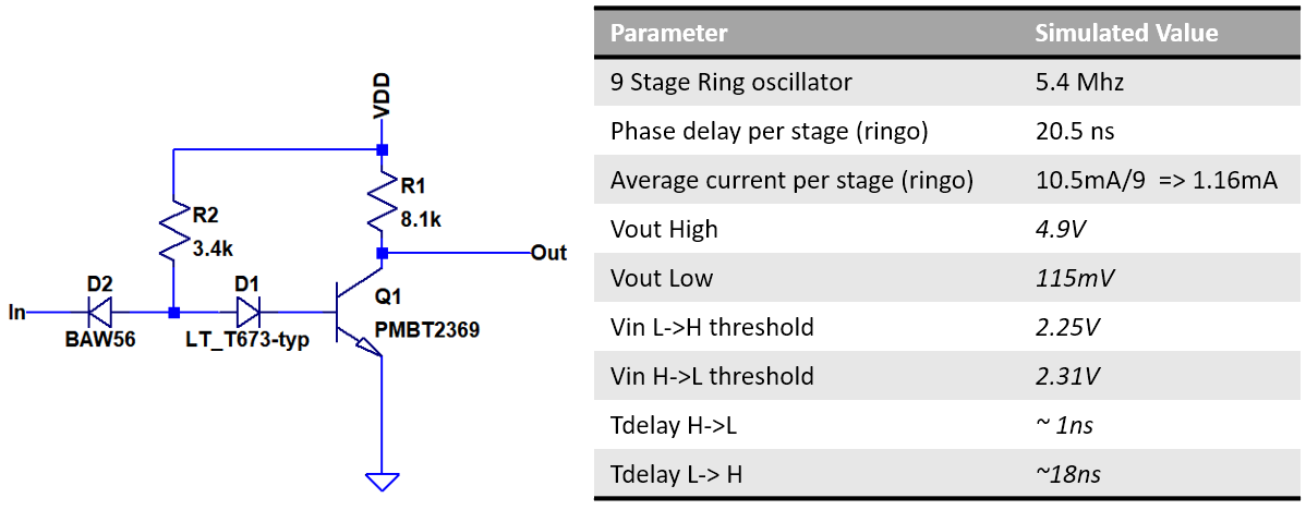
Final parameters of the simulated inverter are shown above. The relatively high L->H delay is owed to the use of a relatively large collector resistor. Note that the threshold voltages are almost centered between the 5V supply and ground, maximizing noise marging and making the gate compatible to CMOS logic levels.
Discussions
Become a Hackaday.io Member
Create an account to leave a comment. Already have an account? Log In.