 Radu Pascal
Disclaimer
The build instructions assume that you have basic experience with soldering, good knowledge of electronics, and Arduino programming. Also you'll need experience with RCs, have an RC Remote and receiver (at least in our prototyping phase). Also you need a 3D printer or a friend who has one.
You also have to be proficient with hand tools, electrical tools, be knowledgeable of safety when working with equipment that might harm you, your cat, your house or your neighbours. If you saw off your hand, blow the fuses in your house, drill holes in your kitchen counter, etc., it's all on you.
The given list of components is mostly for reference. These are the components that either the author decided are best, had laying around, were easy to get, etc. You can decide on your own setup if you know what you're doing. But always check voltages, power ratings, amps draw, etc.
If you do start building this project, please DO NOT EXPECT HELP. It very much depends on the availability of the author, his mood, day of the month, phase of the moon, planets alignment and earth energy fields.
Build Phases
Building is done incrementally, by building a setup and testing parts of it before adding something else. For ex, first milestone is to make it remote controlled, and test the cutting performance, energy performance, drive system - the choice of motors, excessive vibrations, etc.
Only when I'm happy that so far it performs acceptably, I'll move on to making it autonomous by adding sensors, image processing with ESP32. In that phase I will check that the system is feasible - meaning it can cut down a area large enough, I'd be happy with 500-1000m2.
Third phase would be adding a charging station, correctly navigating to it and docking.
Though it's on my mind making the system weatherproof, it will be done when everything else is working as expected
Design Notes
Motor Driver BTN-7960B
A note that I found on a website carrying this board:
To reach the high current, junction temperature must remain low. The BTN7960 module has small heat sink which is not enough to reach 10A to 43A range on a consistent manner. If you need continuos high current capability, better cooling technique (e.g. air flow, water cooling, etc) should be employed.
Note from myself:
Chinese are notorious for scrudging on thermal paste, remove the heatsink and check that enough has been applied!
Cutting Element
I went with a triblade for cutting bushes because.. well, just because it looked cool. I've seen people use paper cutter blades, and I definitely need to try that. Note: the cutter blades have 6mm hole, will design a mount for that.
NEED TO REDESIGN after latest test.
Vertical Motor
The big beefy motor is producing sparks, and I have no idea why (my basic knowledge of electronics doesn't stretch that far). Need to put the oscilloscope on the power lines to check if there aren't spikes introduced back into the system, that might affect arduino.

 EK
EK
 Russell Cameron
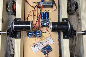
 David
David
 Junglist