0%
0%
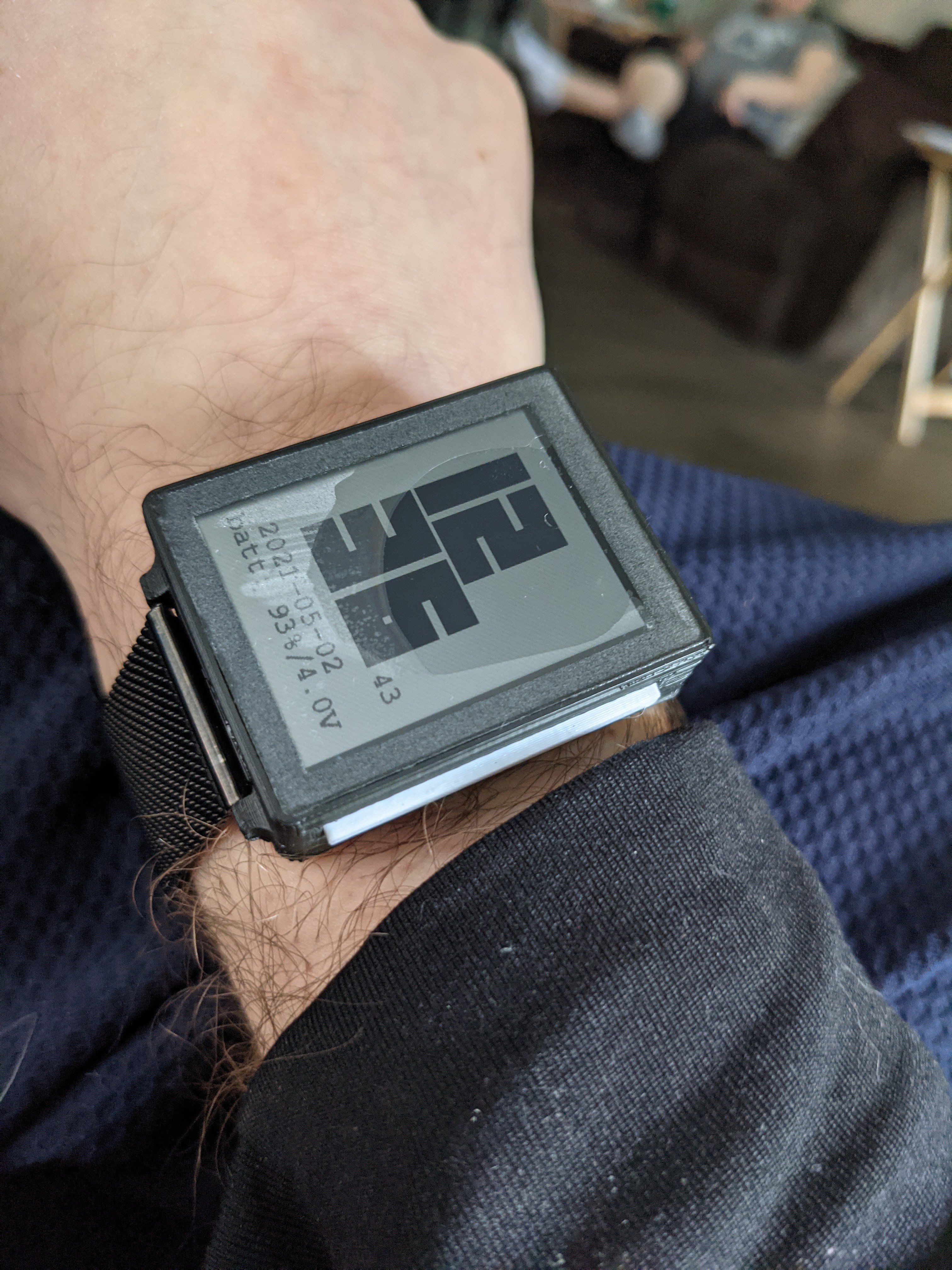
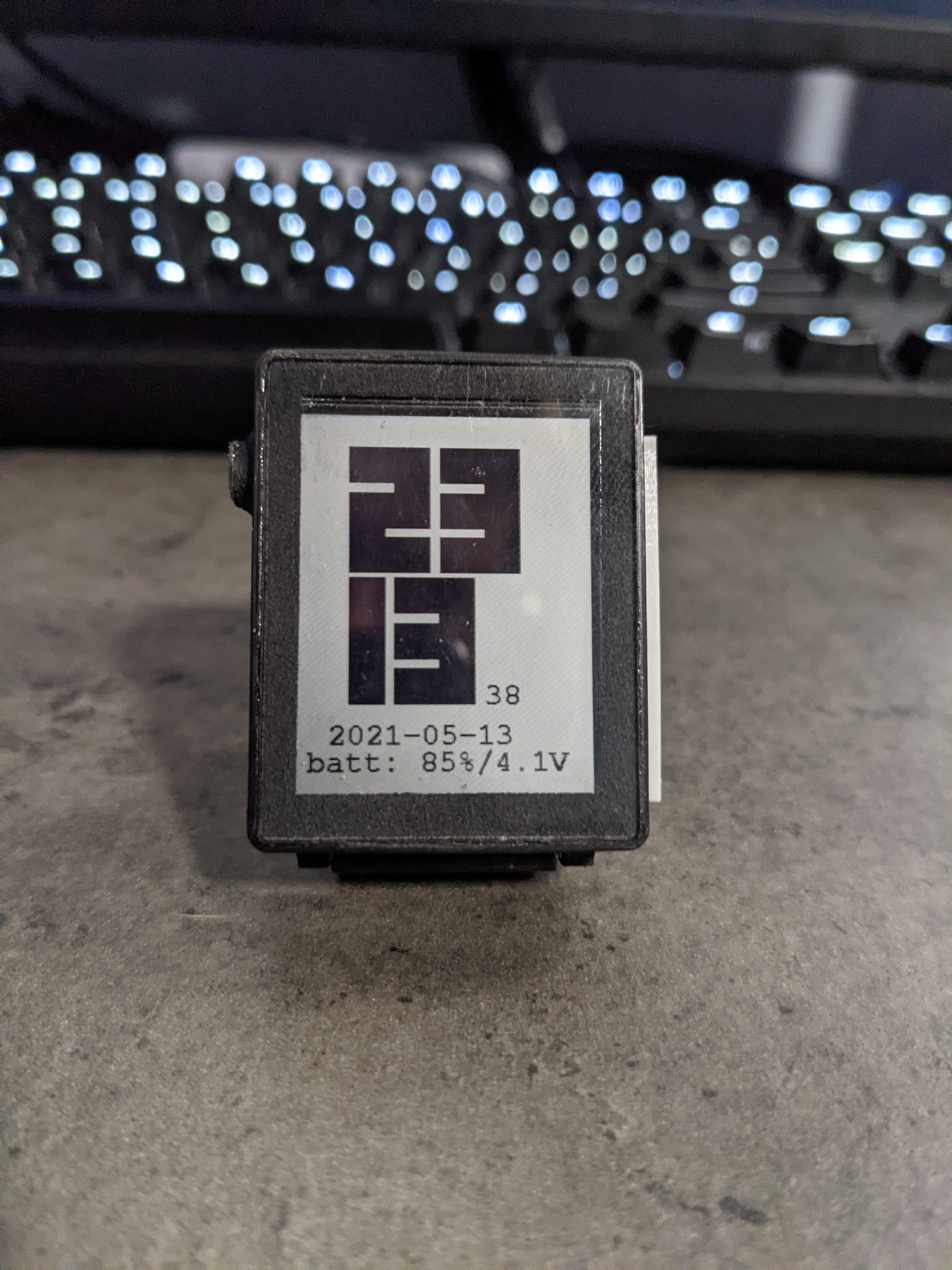
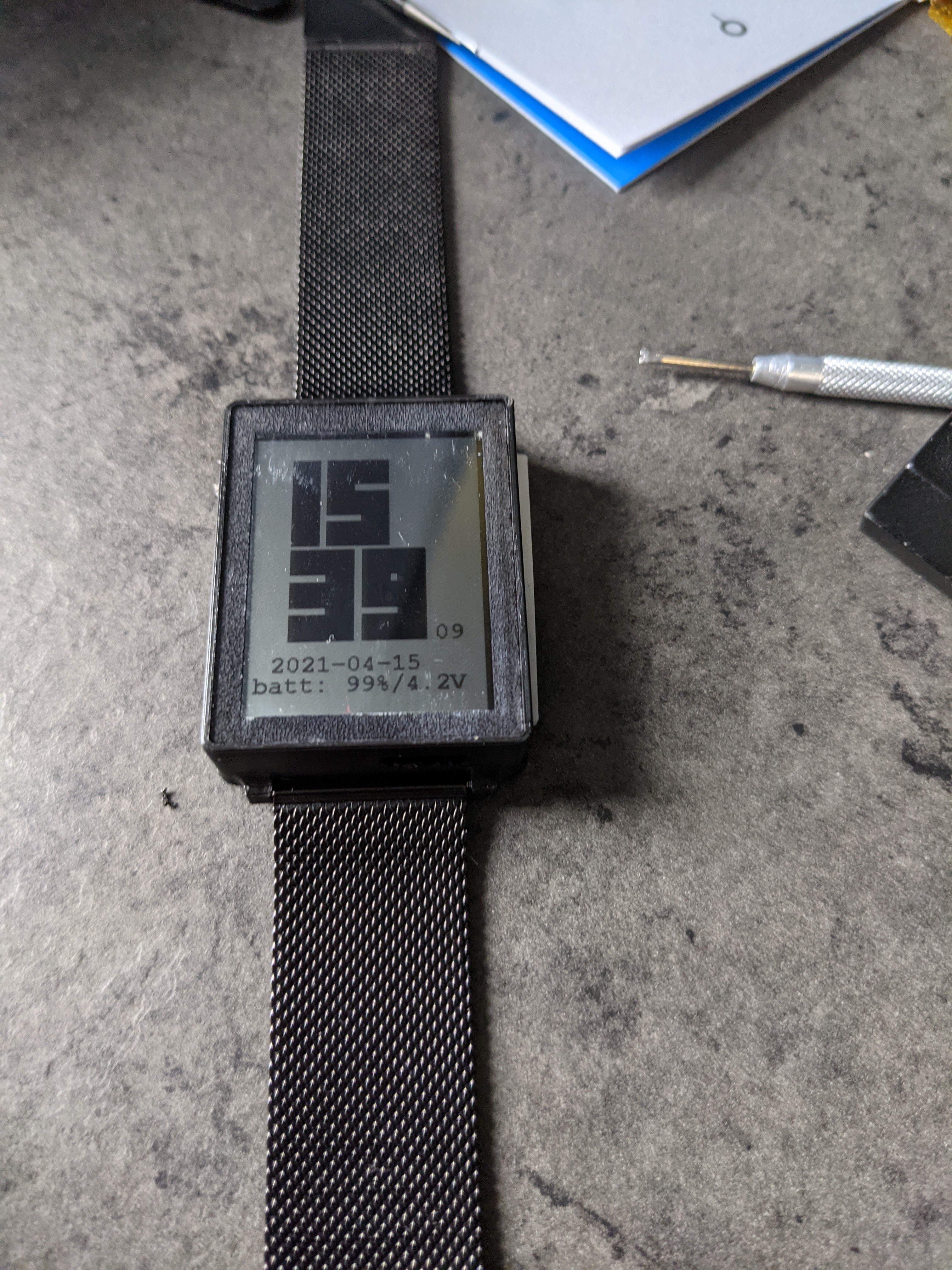
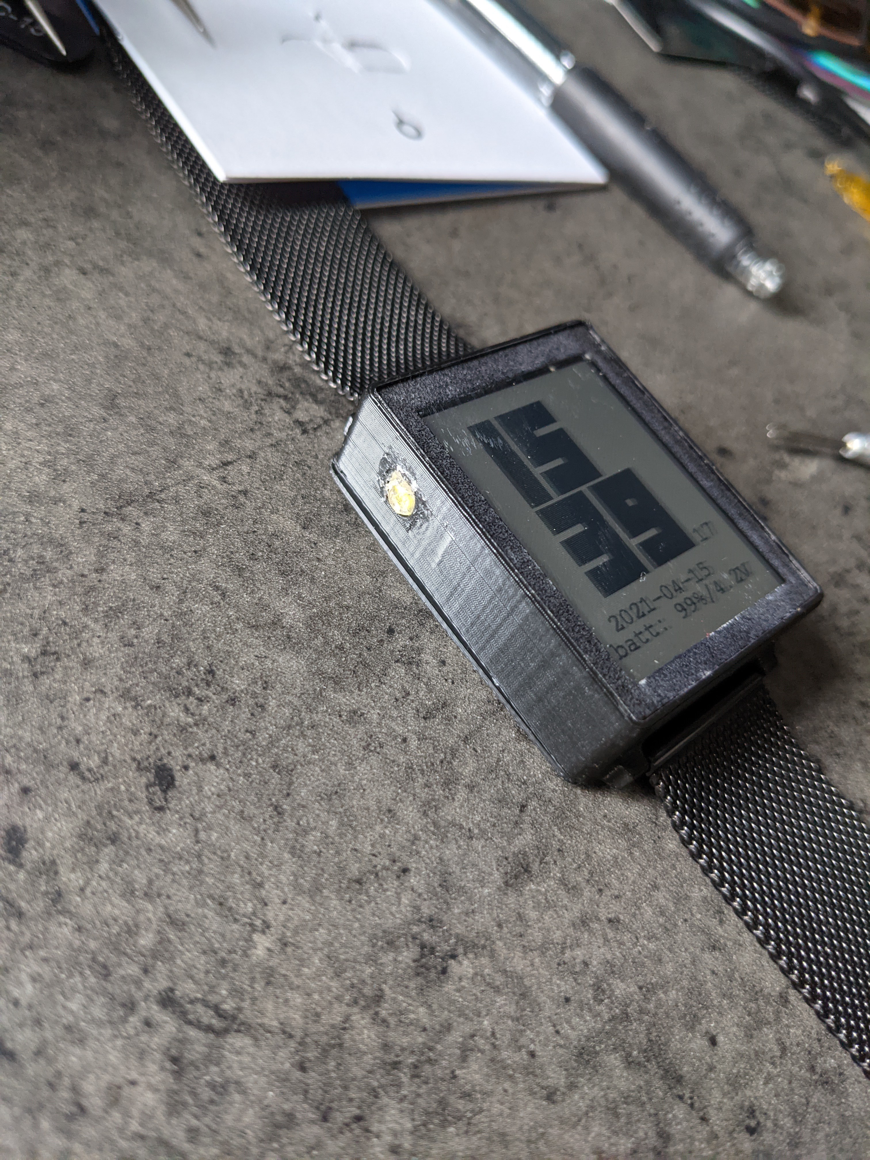
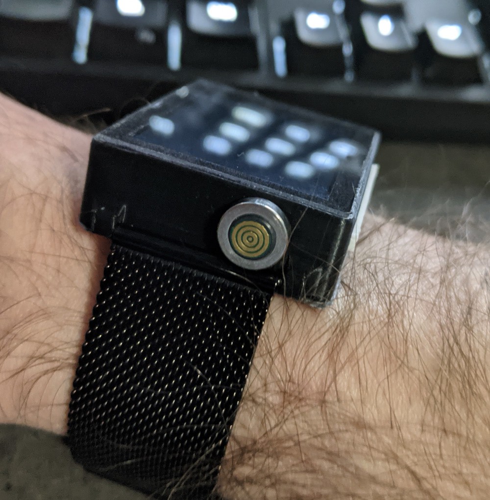
nRF52 SmartWatch
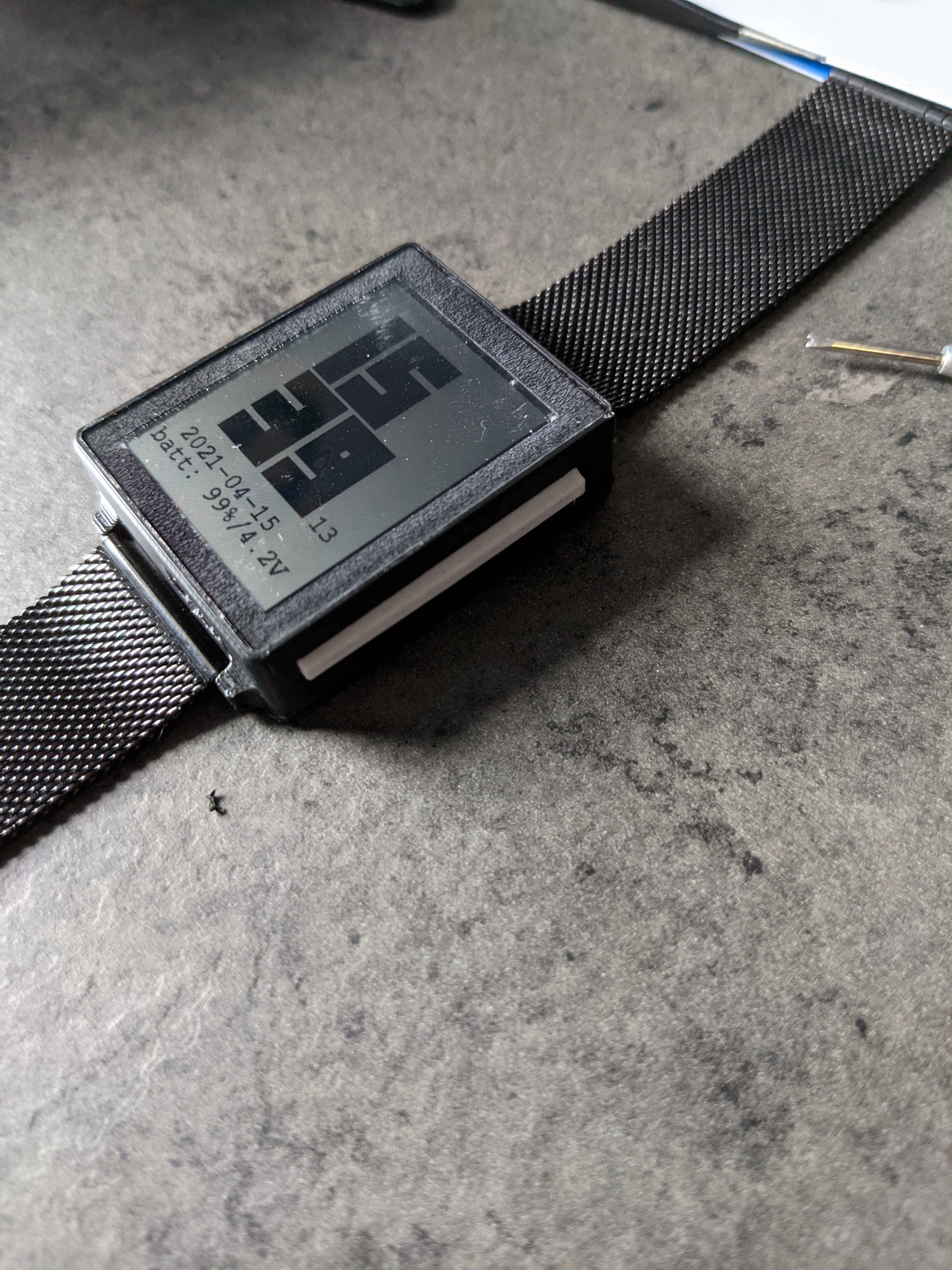
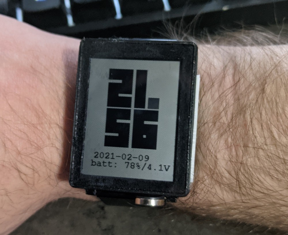
nRF52 Smartwatch from Scratch
 Jeff Cooper
Become a Hackaday.io member
Already have an account? Log in.
Just one more thing
To make the experience fit your profile, pick a username and tell us what interests you.
Pick an awesome username
hackaday.io/
Your profile's URL: hackaday.io/username. Max 25 alphanumeric characters.
Pick a few interests
Projects that share your interests
People that share your interests


 mkdxdx
 ipaq3115
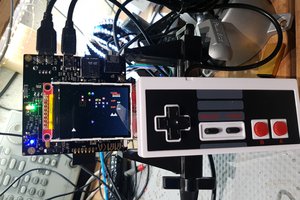
 charliex
 Jon Kunkee
Not a big smartwatch guy myself -- I have a fitbit i was gifted so i wear it. Proves useful as a health monitor -- that's for sure, but as far as watch -- you have the time on your phone. check it.
Anyways, I love how your project is a brick on your wrist. I like it + you like never have to charge it. Give me one!