 Jeff Cooper
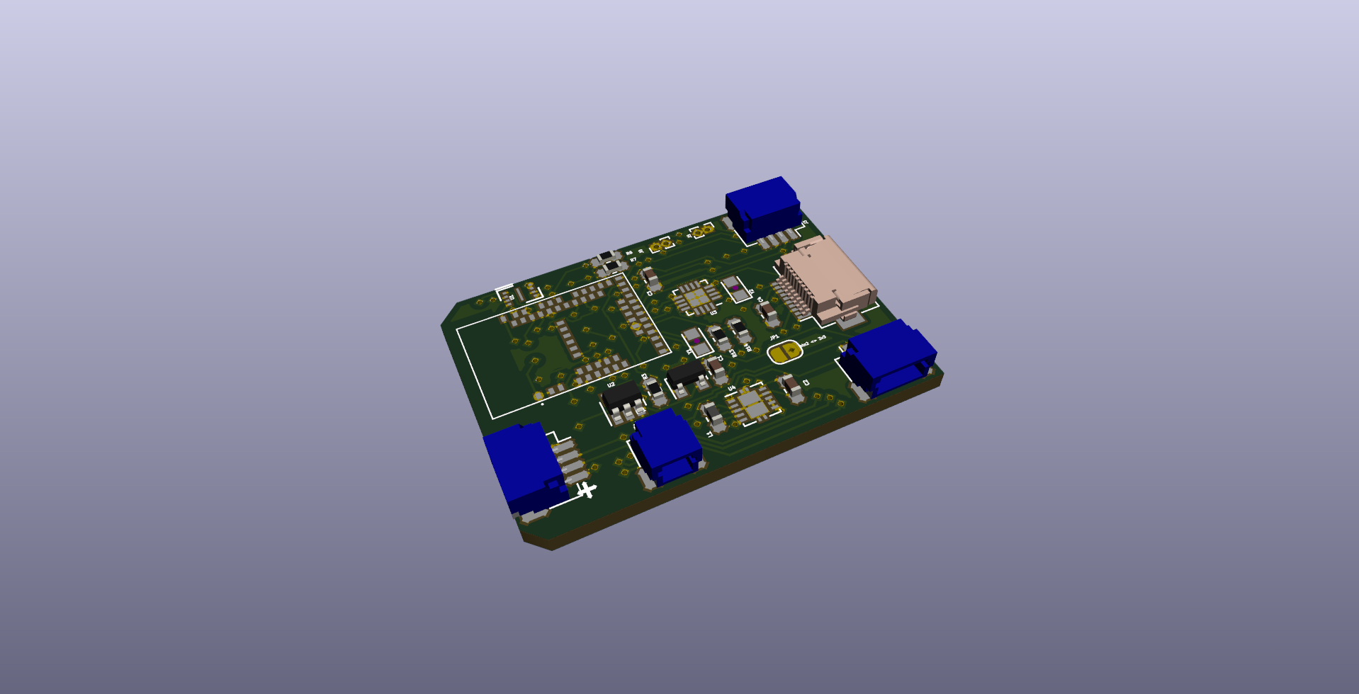
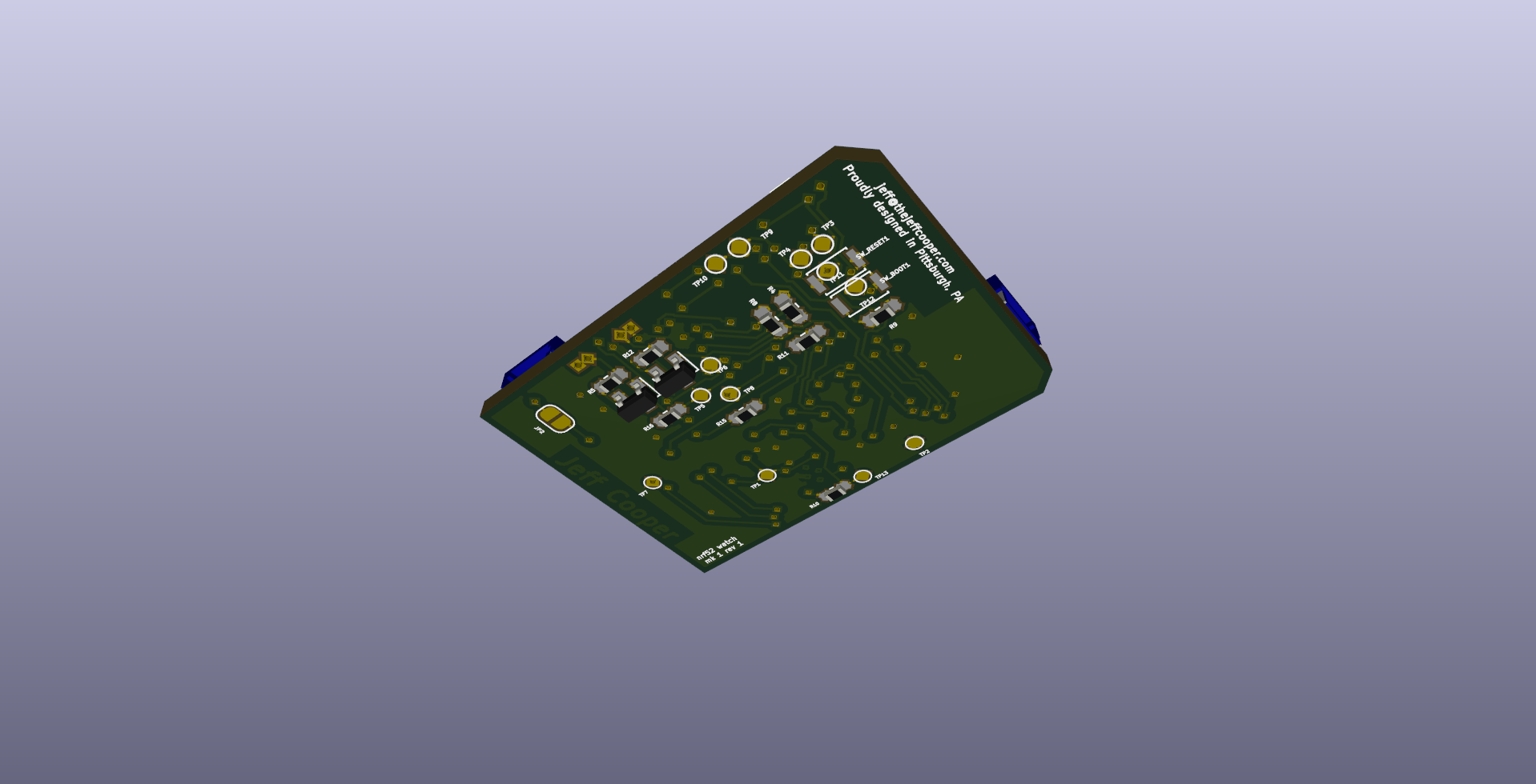
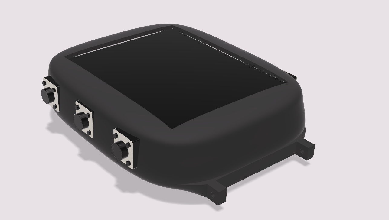
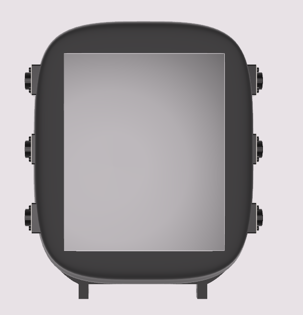
Everything is still a work in progress, and some things I haven't even started attempting. But the PCB is mostly done (I may have to go back and add a 5v boost converter after all), and the case is starting to take shape. Here are some renders so far, because every project needs aspirational renders.
The side buttons are definitely placeholders. They might make it to the first prototype, since those 6mm SMD buttons are super common, but eventually I'll probably CAD up some custom buttons that recess into the case, and put in some low-profile buttons on the PCB.
The buttons connect on identical daughterboards with JST-SH 4 pin connectors (the blue connectors on the right side of the first screenshot). By default, each pinout is 3GPIOs and one ground, but I included a jumper for each that connects one of the GPIOs to 3v3. I strategically chose this layout such that, with the jumper connected, the connector becomes a Qwiic-style connector (I'm not sure I meet the official criteria on that page to be "qwiic-compatible," so let's say it's "qwiic interoperable" -- the pinout is the same). This will let me replace one of the button panels with an I2C board. Unfortunately, I can only use one or the other; the nrf52840 only supports two hardware I2C peripherals, and one is currently being used for the RTC module. I'm relatively certain that the right side will remain with the simple 3-gpios-and-a-ground layout, though. Since I wear my watch on my right hand, this is the side that faces in towards my body. I hope to replace the left side (facing out) with something a little fancier, potentially including a flashlight and/or laser pointer. These would require an I2C IO Expander or driver IC, simply because the GPIOs on the nrf52840 can't source enough current for an effective flashlight. By providing a connection straight to 3v3, I can access the full 250mA of the regulator. Will this be enough for a flashlight? That remains to be seen.
The smaller connector near the bottom of the screenshot is the battery connector. This is also a JST-SH connector at the moment, but I may upgrade it to a more standard JST-PH (which is the connector that comes on every LiPo battery) now that I have the space.
I saved that space with the final JST-SH connector, on the left side of the screenshot. This will go to a small USB-C breakout (which is designed and routed, but not included in this post) that I can mount wherever in the case is most convenient, without having to worry about the orientation of the main board (which is already constrained by the short FFC connector on the LCD). The four pins are VBUS, D+, D-, and GND. Since I'm using USB2.0 compatibility mode, the 5.1k resistors between the CC pins and GND are on the breakout. The connections between the two pairs of positive and negative pins on the connector are also handled on the breakout, which saved complexity on the main board. I'm a little worried about the RFI I might get from running USB over wires that can flop around in the case -- they should be 10mm or less, but it's a high-speed signal. If I have issues, I might have to rethink this, but I'm not too worried.
I also got an email back from some helpful people at FLExLighting with some information about the LCD that I got, and a STEP file for the module that I bought. They informed me that the display itself is meant to be run at 5v power, and promised to send a datasheet soon. I sent them picture of my screen, which I'm more convinced than ever is actually broken and not just misconfigured somehow. I'll post an update once I have something more concrete on the display front.
Discussions
Become a Hackaday.io Member
Create an account to leave a comment. Already have an account? Log In.